Table of Contents
Advanced Frame Editor

The Advanced Frame Editor is the 3rd generation of Frame editor to be included in BEYOND. The first generation is the simple editor currently available in the “Create” menu. The second version was too complicated, was included in BEYOND for only a short period of time, and has been removed. The 3rd generation Editor is based on the 2nd generation editor, but is better balanced logically. Laser frames have many things in common WAV audio files. The frame is actually a wave form sent to the X, Y and Color output DACs. The point of a laser frame is like a sample of an audio file. For wave files there are well known editors like SoundForge, Audition and so on. Our Frame Editor is conceptually a wave form editor. No parametric objects (like a MIDI Synths in audio apps) are needed or a local coordinate systems. Conceptually this is similar to what we did before LD2000.
In addition to the classic tools, we have also introduced several new ideas. The first change is the Point. In LD2000 we have point oriented and vector oriented frames. In BEYOND we have “mixed” frames where vector and point data are present together within one frame. You will not see any more “vector oriented” or “point oriented” frames. You can easily use them both together. Technically, this is same object, but a vector has a special attribute “I am vector”. BEYOND turns on special processing for such points.
The next addition is a curve. There are two types of curves in BEYOND - 2nd degree and 3rd degree Bezier curves. The second degree curve is used in TTF fonts. The 3rd degree curve is widely used in graphic editors. The Frame editor has two sets of drawing tools oriented on points and vector/curves.
We added a new color option. For vector/curves you can define the start color of a line and the end color of a line.
We added fading for the vector/curve beginning and ending. There is a parameter for the depth of start fade and for the depth of end fade.
And finally, the frames that use curves and new color options are double-layered. For compatibility with all existing Pangolin systems, a new frame keeps two things - frame definition and rendered frame. The definition has curves and all related options. The rendered frame has only points and vectors, no curves or complex options. This is an automatic process, you do not need to be concerned about its execution. If you do not use curves then the editor use a classic, single layer frame type.
Frame Editor New has a manual picture tracer. It works in a similar was as the LD2000 system, and allows the use of mixed semi automatic and fully manual outlines.
Frame Editor New provides the ability to open a few frame files to simplify moving the frames between the files.
Main menu
File
- New - creates a new animation (frame sequence).
- Open - opens an animation from a previously saved file.
- Append - adds a frame from a file to the end of your animation.
- Open to new tab - opens a file into a new tab.
- Add new tab - adds a new animation (new tab) in the editor.
- Close tab - closes the current animation.
- Save - saves an animation to a file.
- Save as - saves an animation to a file with a specified file name.
- Import - Metafile from Windows Clipboard. Metafiles (WMF, EMF) are a standard for exchange vector graphics in Windows. Corel Draw, Adobe Illustrator do this. You can copy the graphics in some editors and get it into BEYOND.
- Import - Metafile from file. Same as above, but loads the metafile from the file.
- Trace - calls Picture tracer and after the frame is traced, allows you to edit the result.
- Exit - exits from the Frame editor.
Edit
- Undo - undoes last operation.
Points
- Quick Center - moves the selected points to the center of the drawing system.
- Quick Rotate - rotates the selected points.
- Quick Resize - group of commands for resizing the selected points.
- Flip X - flips vertical axis.
- Flip Y - flips horizontal axis.
- Flip Z - flips horizontal axis.
- Blanking optimization - re-arranges the blanking path according to “nearest win” logic.
- Remove too dense points - deletes points that are too close to each other.
- Remove blanking points - removes sequential blanking points. This is a part of a “point to vector” transformation.
- Remove anchor points - removes anchor (duplicate) points. This is a part of a “point to vector” transformation.
- Remove “density” points (Soft, Medium, and Aggressive) - removes points that lie on a line; soft, medium, and aggressive dictate the amount of points removed.
- Mark as Vectors - marks selected points as “vectors”.
- Mark as Points - marks selected points as “points”.
- Enable gradient inside lines - sets the gradient flag for the selected points.
- Disable gradient inside lines - sets the gradient flag for the selected points.
- Edit softline settings… - opens the soft line dialog box.
- Copy points - copies the selected points of the current frame.
- Cut points - cuts the selected points of the current frame.
- Paste points - pastes points from the clipboard into the current frame.
- Select all points - select all points.
- Unselect all points - unselects all points.
- Delete points - deletes the selected points in the current frame.
- Snap to grid - snaps points to coordinate system.
- Snap to points - snaps to points while using the draw tools.
Frame
- Add - adds a new frame to the end of the frame list.
- Duplicate - makes a copy of the current frame and inserts it into the current position.
- Insert - inserts an empty frame into the current position.
- Copy - copies the selected frames to the clipboard.
- Cut - copies the selected frames to clipboard and deletes it from the current position.
- Paste - pastes frames from the clipboard to the current frame list position.
- Extract to new tab - extracts (cuts) the selected frames to a new tab.
- Reverse order of frames - operation works when multiple frames are selected. Changes/reverses the order of the selected frames within the animation.
- Delete - deletes the selected frames.
- Clear - deletes all points in the selected frames.
- Select all frames - selects all the frames in the list.
- Unselect all frames - deselects all frames in the list.
View
- Show points - paints a rectangle at the point position.
- Show Visible Line direction - shows an arrow that indicates the direction that visible lines are drawn.
- Show Point cursor - shows a “cross”, vertical and horizontal line, that helps indicate the cursor position relative to the frame elements.
- Show blanking path - paints blanked lines as gray lines so they are visible in the editors.
- Show Rendered Points - shows rendered points for curves and vectors.
- Show Blanking direction - shows the direction blanked lines are drawn.
- Show As Beams - paints the frame in beam style.
- Show Start/Finish Markers - shows the markers that point to the start and ends of the visible segments of a frame.
- Show Grid as Dots - shows the coordinate system as dots.
- Show Grid as Lines - shows the coordinate system as lines.
- Show cube - shows a bounding cube around the coordinate system. All portions of a frame that do not fit into the bounding cube will not be visible when the frame is outputted.
- Show coordinate system - show/hides the coordinate system.
- Show intersecting planes - shows the main intersecting planes.
- Show Zero Axis - shows the axis direction on the corner of the view port.
- Paint previous frame - shows the previous frame in the editor to help see changes between frames.
- Show scrollbars - shows scrollbars inside the view port.
- Home XY - returns to the default view port position.
- Zoom in - increases the zoom of the drawing pad.
- Zoom Out - decreases the zoom of the drawing pad.
- Zoom to fit - decreases the zoom of the drawing pad.
- Grid Settings - adjusts the coordinate grid settings.
Window
- Menu One view port, Two view ports, Three view ports, Four view ports - defines how many view port windows are visible inside the Frame editor.
Toolbar
| Tool | Description |
|---|---|
 | Create a new animation (frame sequence) / Open an animation from file / Save an animation to file |
 | Undo |
 | Copy selected points / Paste selected points / Delete selected points |
 | Show points / Show blanked lines |
 | Show curve handles |
 | Snap to points of the frame |
 | Snap to coordinate system |
 | Show laser cursor |
 | Point spacing/density for point oriented tools |
 | Radius of action. This is a parameter enabled when corresponding tool active |
 | Frame Analyzer |
 | |
 | Set projection zones for output |
View port toolbar
| Tool | Description |
|---|---|
 | Sets the view port projection focus; such as Front, Left, Top and other |
 | Sets alignment values for view port angles. When you rotate the view port, the angle will be aligned by the specified value |
 | Rotates the view port |
 | Moves the view port |
 | Zooms the view port |
 | Enables perspective view in the view port |
 | Shows the cross-cursor |
 | Animates the selected points |
 | Opens Background picture menu |
 | Maximize/restores view port |
Slider mode buttons
| Tool | Description |
|---|---|
 | Sets the mode for the view port sliders - position, rotation or depth |
Draw tools
| Tool | Description |
|---|---|
 | Freehand tool. Hold the CTRL key to set a Beam point |
 | Curve tool. Draws a single 3rd degree curve. Hold the CTRL key to align the line to view port align value |
 | Spline oriented freehand. At the end of draw, the editor will transform the freehand path into a sequence of curves |
 | Polygon. Each mouse click adds a new point to the polygon. If the mouse button is held down, this tool will work as Freehand. Right click - stop polygon |
 | Curve oriented polygon. Operates with 2nd degree curves. Great for logo tracing. Hold the CTRL key to add a point instead of curve base; this allows you to add a sharp corner |
 | Curve oriented polygon. Operates with 3rd degree curves. Click to add a new base point to a polygon. Important: after your mouse click that adds the base point, do not release the mouse button, instead - move it, and it will control the spline handles |
 | Vector oriented line. Hold the CTRL key to align to the angle you desire |
 | Vector oriented rectangle. Hold the CTRL key to make a center based frame, hold SHIFT to make a square |
 | Curve based ellipse. Hold the CTRL key to make a center based frame, hold SHIFT to make a circle |
 | Point oriented line. Hold the CTRL key to align to the angle you desire |
 | Point oriented rectangle. Hold the CTRL key to make a center based frame, hold SHIFT to make a square |
 | Point based ellipse. Hold the CTRL key to make a center based frame, hold SHIFT to make a circle |
 | Text tool |
 | Parametric tools. Allows drawing by means of standard, predefined objects |
 | Moves the Guide lines. For deleting - move the line outside of the view port |
 | Select tool. Click on a visible point - select a segment. Hold the CTRL key to add to the selection. Click on empty space for rectangular selection |
 | Lasso selection. Draw a free form area and the points inside the area will be selected |
 | “Gravity” tool. Editor shows a circle. Points inside the circle will be slowly pushed out from the circle. Hold the CTRL key to do the opposite action |
 | Point tool - designed to move single points or lines |
 | Split line or curve. Click inside any line or curve and the editor will add a point. You can also move the point in this mode |
 | Delete a point |
 | Moves selected points |
 | Rotates selected points |
 | Resizes selected points |
 | Recolor multi-tool. Click on a line to recolor it with the selected color. Click on empty space, lasso tool, and then recolor. Click on line(point) with CTRL to recolor a segment |
 | Lasso based recolor tool |
 | Rectangle based recolor tool |
 | Pick a color, click on line or point and edit to use this color (eye dropper tool) |
 | Fill tool |
 | Blank / visible. Based on Gravity tool. All points within the circle-cursor will become visible. With CTLR held the points will be Blanked |
 | Spray tool. A soft recolor, based on Gravity tool. Points within the circle-cursor will slowly be recolored to currently selected color |
 | Eraser, still in test mode |
 | Tracer tool. See chapter about tracer |
Color Panel
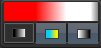
Color panel shows the current selected color and mode. Left button enables a start fade, the middle button enables gradient mode, and the button on the right enables a finish gradient. The gradient and fading work for vectors and curves. Click on the panel to open the Color dialog box.
Coordinates and Locks

Coordinates show the current cursor position in the view port. Lock allows you to disable the change of X, Y, or Z coordinates while using tools such as move, resize, and rotate.
Color palette
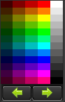
The Frame Editor has a few color palettes that you can choose from by means of Left/Right buttons. Click on the panel change current color that is being used for drawing tools.
Guide lines

The guide lines can be used to markup the drawing area. The mouse cursor will snap to the guide lines. For adding guide lines, click and drag the short blue line to the center of view port. For changing the guide line position use corresponding draw mode tools.
Animation properties tab
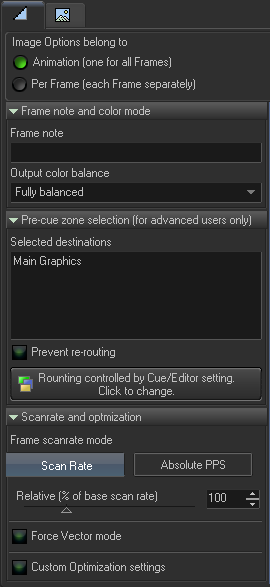
The Animation properties tab is an extended version of the Image Properties dialog. The Animation properties have a specific option that defines (who has) Image properties.
- Animation - means that there is one common Image property for all frames inside the animation.
- Per frame - means that each frame has its own settings, and Animation settings have no action.
Pre-cue zone selection
Image properties also include a zone selection. For LD2000 users, it known as the “preferred zone”. If the animation is used inside a Cue, then the cue has its own zone settings. The Cue settings have a higher priority than Animation settings, and if a Cue’s zone settings are defined (not empty), then the Animation level setting will be ignored. If you need to use an animation setting then leave the Cue settings empty. Please read the chapter about Routing. Other settings inside Animation tab.
The Animation properties tab is a copy of the Image Properties dialog. Please read the chapter about Image Properties.
Point property tab
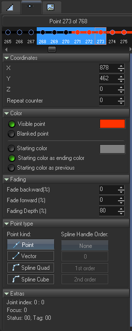
At the top of the Point properties tab there is a point list. Here you can select one or more points and make changes to them. All changes made in this tab are applied to all the selected points. The point list shows the color of the point. Current points have a selection rectangle, all selected points have a blue background.
Coordinate panel
- X, Y, Z - coordinates of points.
- Repeat count - number of times to repeat this point when outputting.
Color
- Visible point - this point is visible and has color.
- Blanked point - this point in invisible and is a part of a blanked part.
- Starting color - defines a color in the beginning of the line. In this mode there is a gradient between the start and end (points).
- Starting color as ending color - default state, the line has the same color.
- Starting color as previous - the color of the line start is equal to the color of the previous point.
Fading
- Fade backward - fade applied in the line beginning. Fade forward - fading applied in the line ending. Fading depth - how much to decrease the brightness within the fade.
Point type
- Point - simplest type, the point without any additional processing. Vector - vector, includes spacing, anchor, and corner optimization. Spline Quad - second degree curve.
- Spline Cube - third degree curve. The option Spline Handle order defines the relation between the handles of the curve base point.
Frame list
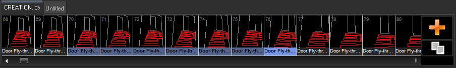
Frame list shows the Frames of the animation. Frame related operations will be applied to all selected frames. For adding new frames, click on Plus icon at right of the list. For duplication of the currently selected frame, click on the “Copy” icon. To delete the frame, click on the Delete button on keyboard. The Frame List has a context menu with all frequently used commands.
All commands related to the Frame List are located in main menu Frame.