Table of Contents
Lasershow Converter Blender
Lasershow Converter Blender Installation
Blender is being updated constantly, so at any point in time the newest version of Blender may not be compatible with our installer. Therefore it is best to use the Long Term Support (LTS) versions of Blender.
The current version of Lasershow Converter Blender supports LTS version 3.3, and 3.6, as well as newer interim versions 4.
- Install a Long Term Support (LTS) version Blender, which can be found here:: (https://www.blender.org/download/lts/)
- Run the Lasershow Converter Blender installer (LCBlender_install.exe), which can be found in the InstallSupport folder where BEYOND is located. Or located on the wiki at the Download Center.
- Start Pangolin BEYOND first, and then start Blender.
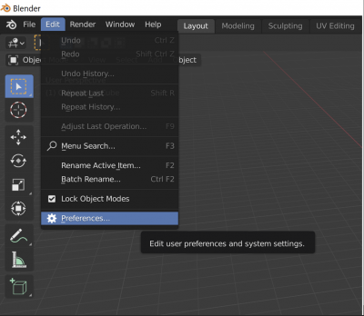
- In the main Blender window, select Edit on the main menu, and go to Preferences
- In the Add-ons section, in the filter dropdown list, select Render:
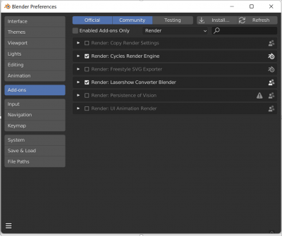
- To enable Lasershow Converter Blender, check the box located to the left of Render: Lasershow Converter Blender.


Activating and Controlling Lasershow Converter Blender
- On the Properties panel, open the Render tab:
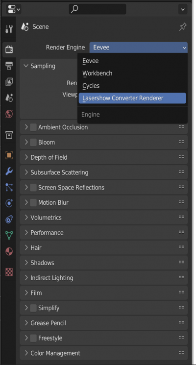
- From the Render Engine drop-down menu, select Lasershow Converter Blender
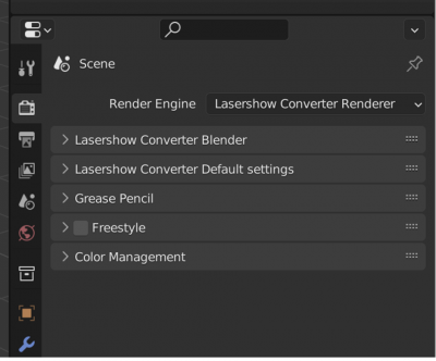
- On the Render Properties panel, you will see the following panels:
- Lasershow Converter Blender
- Lasershow Converter Default settings
- The main Lasershow Converter Blender panel is shown and described below:
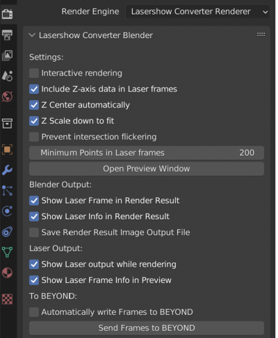


Settings
- Interactive Rendering – Allows Lasershow Converter Blender to immediately render, if you make any changes to parameters in the add-on.
- Include Z-axis data in Laser frames - Includes the Z-axis data in the laser frame, which might be especially handy when making old-school wireframe laser frames.
- Z Center automatically - the plugin automatically calculates the center of the scene along the Z axis, when you have opted to include Z-axis data.
- Z Offset (Blender coordinate space) - Alternatively you can specify an exact Z-axis coordinate (in Blender coordinates) that will correspond with the center of the Z-axis in the laser frame.
- Z Scale down to fit - Similar to the Z-Offset options above, the Z-axis output may be automatically scaled to the typical laser coordinate space.
- Z Scale Factor - Alternatively, you may specify the scale factor correspondence between Blender coordinates and laser coordinate space.
- Prevent intersection flickering - Changes a few internal rendering parameters so that intersections will not cause flickering lines when objects are created with perfect placement.
- Minimum Points in Laser frames - This sets the minimum number of laser points rendered in each frame.
- Open Preview Window – This button opens a preview window, which shows the rendered laser frames and may also show additional information such as the Z-axis coordinates and number of points in the frame.
Blender Output and Laser Output
- Show Laser Frame in Render Result - After starting rendering, a new window will open called Blender Render, which shows the render result. Lasershow Converter Blender can display laser frames and animations in this window. Note that rendering into this window slows things down, so you can uncheck this box for faster rendering. If you uncheck this box, then you will only see a gray background in this window.
- Show Laser Info in Render Result - Shows laser frame information, such as Z-axis coordinates and the number of points, at the bottom of this window
- Save Render Result Image Output File - If the image output to the Blender render window is enabled, then a single frame or animated sequence laser frames can be saved according to the settings in Blender Output Properties. The path to save the render result image file when 'Save output render result image file' is set is in Blender's 'Output Properties' panel: Rendering » Render Output » Output Properties » Output
- Show Laser output while rendering - Allows you to see each frame of the animation, as it is being rendered. Once the rendering process is complete, laser output will continue to be displayed until this check box is unchecked.
- Show Laser Frame Info in Preview - This tells the plugin to show the number of points in the laser frame, along with the Front-most Z-axis and Rear-most Z-axis in the presently selected frame. The Z-axis information is particularly helpful when using Beam Brush.
To BEYOND
- Automatically write Frames to BEYOND – Allows you to automatically send frames of the laser animation to the selected cue in BEYOND, every time rendering is completed. (This can be annoying if you have Interactive Rendering enabled…)
- Send Frames to BEYOND – Clicking on this button will send frames of the laser animation to the selected cue in BEYOND. Using this button allows you to control precisely when the completed animation is sent to BEYOND.
Setting render default options
Default Settings are applied to all objects in a scene, unless those settings are overridden at the Object level, or, for Grease Pencil objects, the layer level.
The Lasershow Converter Default settings panel is shown below.

Render Source:

Render Source defines the type of scene objects that will be used in the rendering process:
- Geometric Objects – Uses mesh data in the scene, and allows for the fastest rendering possible.
- Freestyle Strokes - Lines that are output from Blender's built-in Freestyle renderer will be used as an input to Lasershow Converter Blender. (Note that this requires Freestyle to be enabled in Blender, and additional properties to be set to allow Freestyle to generate lines in Blender.)
Line Types

- All polygon lines - Creates a line anywhere that a polygon edge exists.
- Silhouette: Silhouette Creates a line that surrounds the boundary of the object, from the current viewpoint.
- Silhouette: Silhouette + Folds Creates a line the surrounds the boundary of the object, and also creates any lines as a result of folds in the object.
- Silhouette: None - no lines are generated that correspond to the silhouette of the object.
- Creases - Creates a line along the edge of two adjacent faces, based on the angle between those faces.
- Crease Angle - angle between two adjacent faces.
- Intersections with other objects - Creates a line where two objects intersect.
- Color mode - Color of intersecting lines drop-down list.
- First drawn Object: Uses the color of this object (if it was created before the other object)
- Second drawn Object: Uses the color the other object ( if it was created after this object)
- Farther object: Uses the color of the object that is farther away from the viewer.
- Closer object: Uses the color of the object that is closer to the viewer.
- Intersections within the same object - This is similar to the option above, but this option creates lines where two surfaces within the same object intersect.
- Material Change - Creates a line where there is a material change within an object. Usually, objects have only one material assigned to them. But it is possible to assign multiple materials to the same object.
- Marked seams - Creates a line along the marked edge. To mark an edges as a seam, press Ctrl + E to access the Edge menu and click Mark Seam.
- Contours - Creates lines that run across the surface of an object. These lines are of a constant height increment. The number of contours is controlled by the spinner and text box beside the Contours option.
- Show Backfaces prevents hidden line removal from happening within the selected object. This makes the object look like a typical 3D laser frame with no hidden line removal within this object. Note that even though there is no hidden line removal within this object, this object will still hide other objects because it is not defined as Transparent.
- Transparent prevents this object from hiding other objects behind it. This is useful for creating transparent domes over other objects.
- Prevent Errant Lines prevents extra lines from appearing on meshes with degenerate polygons.
- Prevent Laser Output calculates the object, but does not actually write any data (points) to the laser frame. This lets the object mask or intersect other objects, without being seen. In a sense, the object becomes “black”.
Filter Setting

Lasershow Converter Blender includes several filters to aid in the creation of smooth paths for the laser to follow:
- Gap filter distance - Allows the laser to jump across small gaps in the lines generated for the laser. Increasing this number allows the laser to create longer more-continuous paths from otherwise lines that have interruptions in them.
- “Overlap filter distance - defines the number of beam diameters that Lasershow Converter Blender will search while identifying overlapping lines.
- Overlap angle filter - defines the maximum angle (in degrees) and Lasershow Converter Blender will consider when identifying overlapping lines. Most of the time, this should be set to between 20 and 45 degrees. Sometimes you will need to increase this, especially when dealing with complex meshes with lots of overlaps.
- Noise filter Minimum length - defines the number of beam diameters that Lasershow Converter Blender uses to consider whether a line should be drawn or not. For example, if the Minimum Length is set to 3.0, Lasershow Converter Blender will not generate any points on the laser display if a line is less than 3.0 beam diameters long.
- Filter across objects - Removes lines that essentially overlap as a result of two objects being right next to each other, but not touching.
Color Setting
- Visibility - The coefficient of visibility of all lines of the object (ranging from 0.0 to 1.0).

- Color Settings:
- Object (or Material color) - Object line color determined by Blender settings found in the Materials panel, including diffuse color, emission color, or an actual ImageTexture.
- Custom Color - Allows you to specify your own color, and opens the color selection dialog, which will be assigned to all objects on the scene.
For example:

- Light Settings - The dropdown list has three options

- None - Color without lighting calculation.
- Light shading - Color calculated taking into account lighting.
- Light shading + Shadows - Color calculated taking into account lighting and calculating shadows on objects.
- Replace Black Color – For Grease Pencil strokes that are black, you can choose a replacement color.
Point Spacing

AutoBlank Points
AutoBlank Points at line beginnings and at line endings specifies the number of blanked points that will be automatically placed at the beginning and ending of lines (respectively) on square objects. These blanked points are all placed on top of each other, at the starting and ending location of the line.
AutoBlank Points at round overlaps is the number of blanked points that will be automatically placed at the beginning and ending of rounded objects. These blanked points are not placed on top of each other, but instead are drawn the same way the object is in order to hide where the drawing started and ended.
If you set this value to 0, no closed contour optimization is used. Instead, the object is always drawn using AutoBlank Points at line endings and AutoAnchor Points.
AutoAnchor Points
AutoAnchorPoints at line beginning is the number of points that are placed at the beginning of a line.
AutoAnchorPoints at line ending is the number of points that are placed at the ending of a line.
AutoAnchorPoints at round overlaps is the number of extra points that are placed at the point of overlap of a circle or other rounded object. Normally this is set to zero so that you can't see where the beam starts or ends. But if you are using scanners that are not tuned perfectly, you may actually see a visible gap on circles. Increasing this number will hide the gap on poorly tuned scanners but this may actually cause a visible overlap on well-tuned scanners.
AutoAnchorPoints at various angles, is the number of additional points placed at various angle corners. There will always be at least one point at every corner. For example, a setting of “4” means there will be a total of 5 points placed at that corner.
The Accelerate/Decelerate check box controls how the points are placed from the starting and ending of lines, and at corners. If this is checked, a special algorithm is used to accelerate and decelerate the beam from corner to corner, and from beginning to ending. When this is checked, it makes the object easier for scanners to scan, and it also reduces the number of corners and beginning and ending points needed. This can also keep objects looking good as they zoom out since it automatically controls the number of points along straight lines.
Corner detect ranges from 0 to 100 percent and controls the sensitivity to corners. At 0 percent, no corners are detected; this means the AutoAnchorPoints at various angles will be completely ignored. At 100 percent, any angular change within an object will be considered in light of the angle and AutoAnchorPoints will be placed for these particular angles.
AutoSpace Distance
AutoSpace Distance for blanked lines controls the point density of blanked lines. Lasershow Converter Blender employs a sophisticated point placement scheme for blanked lines that generally allows a lower point density for blanked lines, but also allows the scanner to easily get from one line to the next.
AutoSpace Distance for straight lines controls the point density for visible lines that are completely straight with no curvature.
AutoSpace Distance for curved lines controls the point density for very tiny circles and curved lines.
AutoSpace Curve detect
Lasershow Converter Blender senses the curvature of lines, and automatically adjusts the point density. If a line is completely straight, it uses the straight line density. If a line is highly curved, it uses the curved line density. For lines that are in-between, it will use an in-between point density; this maximizes the efficiency of point placement.
AutoSpace Curve detect controls the sensitivity to curves. The minimum setting of 0 means no curves are detected – the visible density for straight lines is always used. The maximum setting of 100, means Lasershow Converter Blender will place a high density on lines even if they are only slightly curved.
Note that with all of this flexibility, you have the power to create any kind of point placement that you desire. If you desire strictly even intensity over the entire image and “linear” point placement, simply turn curve detect off by setting this to 0. However, if you don’t mind some brightness variation in return for lower point counts in imagery, set this to a value of 20 or higherBeam path for this object
Beam path for this object
This controls the path that the laser beam follows, when drawing the selected object. It is important for animations to have a beam path that is consistent from frame to frame. If the beam path changes substantially from one frame to the next, this will produce noticeable disturbances that could look like jitter, or like missing pieces of the frame, or like flicker. In Lasershow Converter Blender, there are different rules that can be applied to keep the laser path optimized:
- Keep path consistent Uses generic rules to try to keep the beam path consistent (same direction and line traversal order), for each laser frame. In order to create this consistent path, the actual beam path taken in any given frame may not be very optimal. Depending on the object, this could produce a beam path that seems to jump randomly from one line to the next. (The viewer may not be aware of this, since the beam is blanked between lines.)
- Circular optimization Uses special rules that are particularly good for circular or curved objects. Where Keep path consistent may mistakenly reverse the path occasionally on these objects, Circular optimization uses different rules to maintain beam path consistency.
- Linear optimization Rearranges lines somewhat to achieve a shorter path, for each laser frame. This tries to minimize the “jumping around” effect, yet still keep the path direction consistent. This tends to result in shorter overall paths and thus fewer points expended in blanked lines.
- Aggressive optimization Rearranges lines aggressively to achieve the shortest path and the least number of points, for each laser frame. This will have even shorter overall paths. This results in the shortest possible beam path to draw the object. To ensure beam path consistency, some of the rules of Circular optimization are also applied to Aggressive optimization.
Soft Line Setting:

Enable Soft Line must be checked for any of the other settings on this panel to have affect on the rendered object.
Soft Line at line beginning is the number of points over which fading will occur at the beginning of a line.
Soft Line at line ending is the number of points over which fading will occur at the ending of a line.
Soft Line at round overlaps is the number of points over which fading will occur at both the beginning and ending of a circle or other rounded object. Normally this is set to zero so that you can't see any line fading on circles.
Soft Line at line Angle, is the number of points over which fading will occur at the ending of a line and also at the beginning of a line that both meet in a corner. For visual consistency, this should typically be set to the same number as used in Line Beginnings or Line Endings.
Soft Line Minimum Brightness Level specifies how faded the line endings will be. A value of 0.0 means that the corners and endings of the lines are completely black.
Brightness Linearity provides an additional level of control over the fading action. When this number is set to less than 1, a logarithmic ramp is used. When this number is greater than 1, an exponential ramp is used.
Beam Brush Setting:

Enable Beam Brush must be checked for any of the other settings on this panel to have affect on the rendered object.
The Beam Brush can be derived from either Freestyle and Grease Pencil, or from the Z-axis. Each is discussed below.
When Freestyle and Grease Pencil is selected as the Beam Brush Source, the Beam Brush diameter on the laser is derived from the line width of each object. (This is only applicable for Freestyle or Grease Pencil objects.)
Max Freestyle – Limits the maximum value of the line thickness of the object calculated by Blender
Max Grease Pencil - The value of the line thickness of the Grease Pencil object when the value of the thickness parameter for the point is equal to 1.0
Brightness for Min brush % – Brightness of the laser points for very thin lines
Brightness for Max brush % - Brightness of the laser points for very thick lines
Brightness Linearity provides an additional level of control over the fading action. When this number is set to less than 1, a logarithmic ramp is used. When this number is greater than 1, an exponential ramp is used.
When 'Z-axis' is selected as the Beam Brush Source, the thickness value is calculated by Lasershow Converter Blender based on the Z coordinate value for the given point of the object line

Z coordinate of the rear is the Blender Z coordinate that will be mapped onto the far-away dynamic divergence, and also will be applied to the brightness of the object.
Beam Brush rear is the dynamic divergence value that will be used and effectively “mapped onto” the Z coordinate rear specified immediately above.
Brightness rear is the brightness value that will be used and effectively “mapped onto” the Z coordinate rear specified immediately above.
Z coordinate of the front is the Blender Z coordinate that will be mapped onto the near dynamic divergence, and also will be applied to the brightness of the object.
Beam Brush front is the dynamic divergence value that will be used and effectively “mapped onto” the Z coordinate front specified immediately above.
Brightness front is the brightness value that will be used and effectively “mapped onto” the Z coordinate front specified immediately above.
Brightness Linearity provides an additional level of control over the fading action. When this number is set to less than 1, a logarithmic ramp is used. When this number is greater than 1, an exponential ramp is used.
Setting render options for a selected object
Although the default options on the main rendering screen of Lasershow Converter Blender will create good results for most scenes, occasionally you may want greater control over the rendering process, by assigning specific rendering options to each separate object.
Within the Object panel of Blender, you will see Lasershow Converter Object settings. These settings work in exactly the same was as the Default settings described above. You simply check the box next to the respective setting, and then apply relevant settings in each panel.

For example, if you want to select Freestyle Strokes for only a single object, this would be done as shown below:

Setting render options for a selected Grease Pencil Layers
Grease Pencil objects each have a list of 2D layers for grouping and arranging strokes in a List view. Any stroke can only belong to a single 2D layer. There is always only one active layer in the list (the selected one). Custom settings can be set for this selected layer.
In Grease Pencil there are no special mask layers, any layer can act as a mask for other layers. The effect order of the mask in Lasershow Converter is always based on the location of the stroke in 3D space.

Reduce Output Resolution for best results with Lasershow Converter Blender
Setting the size of the output image and animation range Output Properties Blender Panel, we recommend the window size be set to 320-by-320 as shown below. This allows for fast rendering into the Blender Render window, and also allows this window to not take up too much space.

Lasershow Converter Blender only supports the following nodes as material color for objects
Node “PrincipledBSDF” – “Base Color” Color

Node “PrincipledBSDF” – “Base Color” - ImageTexture

Node “Emission” – “Color”

Color Management Settings for consistent color output
In order for the color of the image lines in the Blender Render window to match the color of the lines of the laser frame, you need to make sure settings are as shown below in the panel Render Properties - Color Management:

You need to change the default values to the following:
- View Transform: Raw - Raw provides an output without any color space conversion.
- Exposure - Used to control the image brightness -1
- Gamma - 1
For objects Grease Pencil:
- View Transform: Standard.
- Exposure - Used to control the image brightness 0
- Gamma - 1