
Tools
Support
Pangolin Family of websites
Pangolin Laser Systems, Inc.
Kvant Lasers
Unity Lasers
ScannerMAX
Lasorb
Tools
Support
Pangolin Family of websites
Pangolin Laser Systems, Inc.
Kvant Lasers
Unity Lasers
ScannerMAX
Lasorb
Over the past year we’ve worked hard to improve BEYOND 3D.
We have improved rendering speed by internally implementing Single-Instruction Multiple-Data (SIMD) instructions found in modern Intel processors.
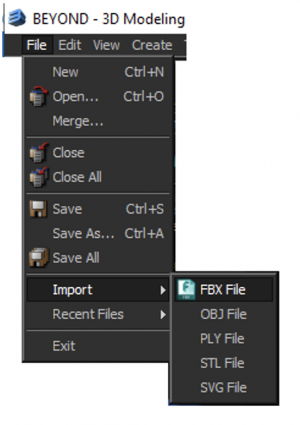
We have increased the number of file formats that can be imported into B3D. We can now import STL (stereo lithography) files, PLY files (Polygon files in the Stanford Triangle format), OBJ files (a standard 3D image format supported by many 3D programs), FBX files (Filmbox files that support both 3D models and animations) and SVG files (Scalable Vector Graphics format). All of these import methods can be found on the File → Import menu.
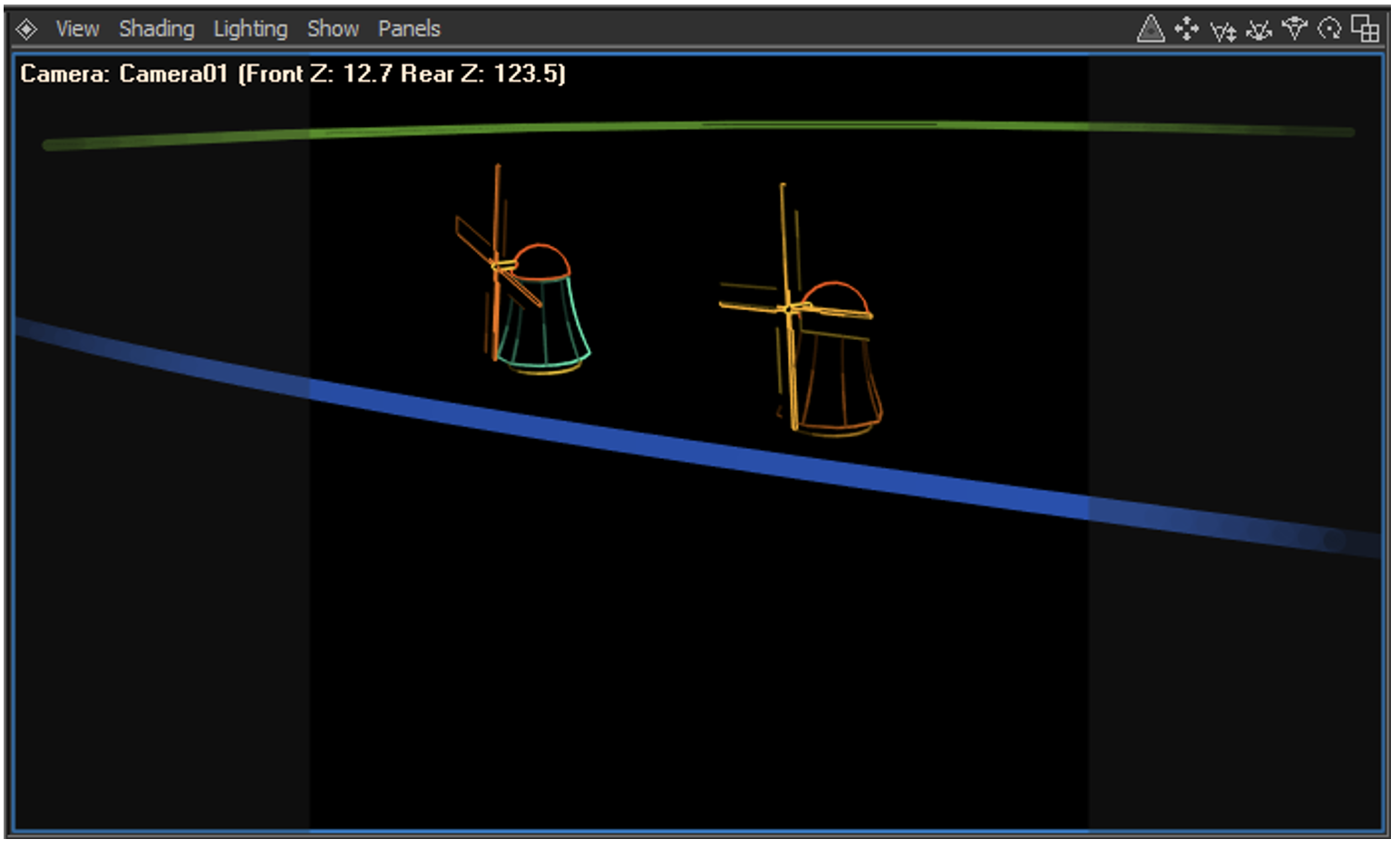
We have also added the ability to show the Z-axis coordinates of the rear-most and front-most elements in the scene. This information is very handy when using Beam Brush. To enable this, use the viewport menu and select Show → Front Z, Rear Z.
We have added Soft Line capability to the Attributes of each object. This allows you to create faded line endings on any object independently. In the Attributes Manager you will see a new Soft Line section just below the Point Spacing section. The Soft Line section is shown below, along with how it affects a wireframe cube.

Soft Line Enable must be checked for any of the other settings on this panel to have affect on the rendered object.
AutoAnchor Soft Line at line beginning is the number of points over which fading will occur at the beginning of a line.
AutoAnchor Soft Line at line ending is the number of points over which fading will occur at the ending of a line.
AutoAnchor Soft Line at round overlaps is the number of points over which fading will occur at both the beginning and ending of a circle or other rounded object. Normally this is set to zero so that you can't see any line fading on circles.
AutoAnchor Soft Line at corners is the number of points over which fading will occur at the ending of a line and also at the beginning of a line that both meet in a corner. For visual consistency, this should typically be set to the same number as used in Line Beginnings or Line Endings.
AutoAnchor Soft Line Minimum Brightness % specifies how faded the line endings will be. A value of 0.0 means that the corners and endings of the lines are completely black.
Brightness Linearity provides an additional level of control over the fading action. When this number is set to less than 1, a logarithmic ramp is used. When this number is greater than 1, an exponential ramp is used.
While the results are completely subjective, and at the whim of the artist using Soft Line Endings, we have experimentally found that a logarithmic ramp appears very pleasing.
Beam Brush is dynamic beam divergence technology manufactured by the ScannerMAX division of Pangolin, and included in certain projectors manufactured by Kvant
We have added Beam Brush capability to the Attributes of each object. The Beam Brush features of BEYOND 3D allow you to effectively map the Z-axis coordinate data from BEYOND 3D onto the beam diameter used to render each object. Each object can have its own Beam Brush settings, providing tremendous power and flexibility. This allows you to create animations that use dynamic beam divergence capability built into Kvant's line of Beam Brush projectors. In the Attributes Manager you will see a new Beam Brush section just below the Soft Line section.
Beam Brush section is shown below, along with how it affects a wireframe cube. You can also see how the Front Z and Rear Z in the Viewport is used as the Z coordinate for front, and Z coordinate for rear, in the Beam Brush section on the right.

Beam Brush Enable must be checked for any of the other settings on this panel to have affect on the rendered object.
Z coordinate for rear is the BEYOND 3D Z-coordinate that will be mapped onto the far-away dynamic divergence, and also will be applied to the brightness of the object.
Corresponding Beam Brush for rear is the dynamic divergence value that will be used and effectively “mapped onto” the Z coordinate rear specified immediately above.
Corresponding Brightness for rear is the brightness value that will be used and effectively “mapped onto” the Z coordinate rear specified immediately above.
Z coordinate for front is the BEYOND 3D Z-coordinate that will be mapped onto the near dynamic divergence, and also will be applied to the brightness of the object.
Corresponding Beam Brush for front is the dynamic divergence value that will be used and effectively “mapped onto” the Z coordinate front specified immediately above.
Corresponding Brightness for front is the brightness value that will be used and effectively “mapped onto” the Z coordinate front specified immediately above.
Brightness Linearity provides an additional level of control over the fading action. When this number is set to less than 1, a logarithmic ramp is used. When this number is greater than 1, an exponential ramp is used.
note that a Beam Brush value of 0 represents nominal laser divergence (typically 1miliradian or less), and a Beam Brush value of 100 represents the maximum divergence that the laser is capable of (typically around 30 milliradians).
We have added a section to the Render Setup dialog box, which allows you to select the inclusion of, and also to control the Z-axis data in, the frames that are generated by BEYOND 3D. This is shown at the bottom of the Render Setup dialog box below, in a section called Include Z-axis data in laser frame.

Since BEYOND includes only a non-photorealisic renderer, it typically creates only two-dimensional output in the laser frames. That is, the laser frames have only X and Y data that change, and normally the Z-axis data is set to zero. However, for certain special effect applications, it may be handy to have BEYOND 3D include Z-axis data. This may be used in BEYOND to map the Z-axis data onto color, onto brightness or other special effects. This may also be used with single wireframe objects which are then further manipulated and rotated in BEYOND.
Enable Include Z-axis allows you to specify whether Z-axis data will be included in the laser frame output. If this check box is not checked, then the Z-axis data is always set to 0.0 in the rendered frames. When this is checked, then Z-axis data is included in accordance with other parameters contained in this panel.
Center automatically, and Scale down to fit provide the quickest and easiest results. When used, BEYOND 3D will simply automatically center the output on the Z-axis and scale it to fit the coordinate space. This is the best choice to use when you want to use the Z-axis data for special effects in BEYOND. Alternatively you can specify an exact Z-axis offset – in BEYOND 3D coordinates – that will correspond with a Z-axis value of “0.0” on the laser.
Similar to the Z-Offset option above, you may specify the Z Scale Factor, which controls the correspondence between BEYOND 3D coordinates and laser coordinate space.