Tools
Support
Pangolin Family of websites
Pangolin Laser Systems, Inc.
Kvant Lasers
Unity Lasers
ScannerMAX
Lasorb
Tools
Support
Pangolin Family of websites
Pangolin Laser Systems, Inc.
Kvant Lasers
Unity Lasers
ScannerMAX
Lasorb
Distributed Scanning is a great method to improve the quality of a Laser Graphics display. Laser displays have a widely known problem: – complex Graphics have many points, a long trace path, and as a result, it is hard for a single Projector to display them. As a result, Graphics must be simple, or the refresh rate drops down, and the image starts to flicker. A typical example of such a problem is found with Text. Text Characters have many corners, and we want to display many characters. Because of this, the image will flicker, and this doesn't looks attractive. Distributed Scanning allows the User to split the workload of displaying the Graphic over two or more Projectors. The advantage of this is part of the Graphic is drawn by one Projector and the other parts, by others, thereby splitting the workload of drawing the graphic over ALL of the Projectors and reducing the workload on each.
Let’s consider a sceptic point. To make a display using several Projectors is already possible. You can sse a Timeline with several Tracks assigned to different Projectors and you can then combine the picture from the parts. No doubt it will work. It is a great classic way. There are positive sides:- You have full manual control over the distribution of the parts by Projector. As a rule, human can manage such decisions as to how to distribute the parts better. However, there is a negative side: - The Projector Output will be not synchronized. Each Projector Output will be drawn at it's own time, own rate. Thus the display will be a bit shifted between Projectors. It will be noticeable more and more as the number of points in frame increases. This is a known problem of the “Also To” feature of BEYOND. The root of problem is the synchronization between the Projectors. Typically, we do not need such synchronization. Just the opposite, we want a solid continuous waveform from the Projector, so called “smooth output”.
Let’s consider the pertinent points of this technology and then how to make it work. The main idea is to take two or more Projectors and split the picture drawing duties between all of them. As an example, Projector one displays points 1…499. Projector two displays points 500..999, Projector three displays 1000..1499, and so on. To work, the Projectors must all start at the same time and draw the picture at the same time. What does it give us in reality? First of all, if the Projector displays 500 points. At 30K it gives us 60 FPS. No flickering. The second consequence is the animation runs smoother than the original. If we have frame with 1000 points then at 30K it gives us 30FPS. With distribution on two projectors, the FPS will still be 60 FPS. It is twice as smooth than with a single Projector. So, even two Projectors make the animation twice as smooth as the original. A third great consequence – the picture looks brighter. It really is, no magic. Instead of one Projector , we use two or more. If we have a 1-watt Projector, then for a standard display without distribution we have 1 watt per Frame. If we distribute the picture on two Projectors, then we have 2 watts per Frame.
Now, let’s consider the requirements.
There are technical problems we should consider. Thermal drift and distance. Large distances might show the limits of resolution. We operate with a digital signal. Resolution is limited. We do not see it because of the nature of the Scanners. A Scanner works as an IR filter that smooths the signal. Thermal drift is a known problem. When Scanners and/or amps heat up, it might create a change in their characteristics. The result depends on the exact device. One of the solutions – is to warm up the Scanners first, by displaying a Test Frame for an hour with zero brightness.
During distributed scanning, the Projectors must all act as one. Only in this scenario we will have a solid picture. Let me make the accent on “one”, because ii answers questions that will pop up later. In practice, we have been following a model. There is a Master Projector, and one or more Slave Projectors. They form a Distribution Group. As soon as the Master Projector starts Distributed Scanning, it “disconnects” the Slave Projector from its' normal Work Flow, and the Master Projector tells the Slave what to display and how. When the Slave Projector is under the control of the Master, do not expect it to display something else. Slave Projectors will not accept any extra load whilst under control of the Master Projector. All the Multiple Projectors must act as one.
OK, let’s do one more step in depth. BEYOND output is based on Projection Zones rather than the Projector. It means that Projection Zones must be involved in the process. Rule: The Master Projector has a Projection Zone that initiates/triggers Distributed Scanning. As soon as you send some Output to this Zone, BEYOND considers it as a signal to start Distributed Scanning. It will disconnect the Slave Projectors from their normal workflow, and connect them to the Master Projector as slaves.
Overall the idea is simple. We send a signal to the Zone of the Master Projector, and this turns on Distribution, and splits the signal between the Projectors. Slave Projectors need to know where to Output the signal, that is why we define Projection Zones for each Slave Projector.
The Distribution Logic for two projectors:- If a Frame has less than 500 points then only one Projector will be used. If the number of points is between 500 and 1000, then the first Projector paints 500 points, and the second the rest. If the number of points is more than 500, then first Projector displays the 1st half, and second Projector the second half.
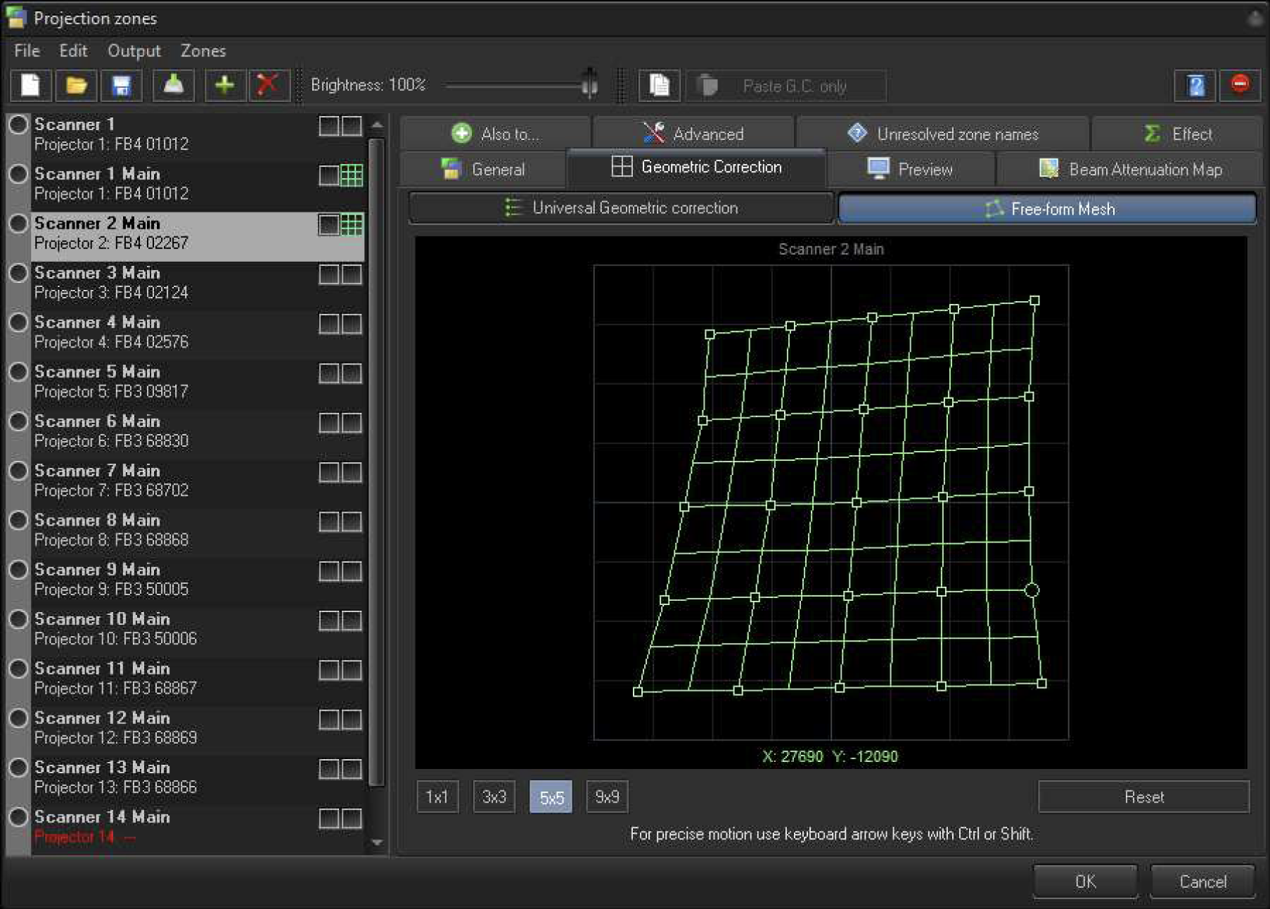
Recommendation for Geometric Correction Tuning: - Set up the Zone of the Master Projector, using the embedded Grid Test Pattern, and leave it enabled. Adjust the Geometry Correction to be as accurate as you need. After that go to the 1st Slave Projector, select the Grid Test Pattern, and select Mesh Correction in 3×3 Mode and adjust the position of the Slave Test Grid onto the top of the Master Test Grid - overlap the corners first, and then center. If there is an offset in the inner areas, select 5×5 Mode. You will have more control points. Repeat the procedure and put the Slave Grid on top of the Master Grid as best as you can. If you need, use more resolution for the Mesh. Once the 1st Slave Projectors' setup is complete, turn off its' Test Grid, and repeat the same process for the other Slave Projectors.

Once Geometric Correction setup is done, it's time to setup a Group.

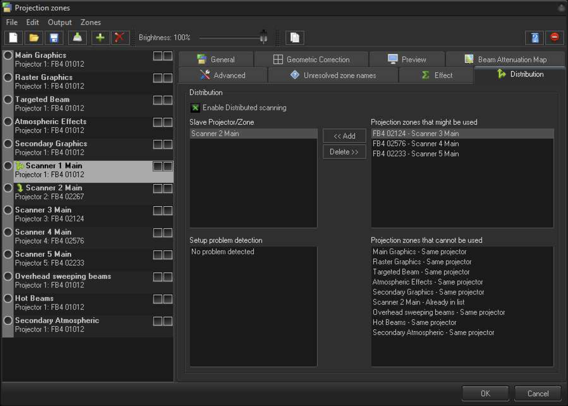
This tab has multiple controls. The setup related controls are located at top side, the informational at the lower side.
The Check Box “Enable Distributed Scanning” enables Distributed Scanning. Click it at the end of the setup process. Pay attention, Distribution is disabled whilst the Projection Zone Dialog is active. Otherwise you would be unable to setup Geometric Correction.
“Slave Projection/Zone” lists one or more Projection Zones that act as Slaves in the Distribution Group.
IMPORTANT For Distributed Scanning, it is mandatory to setup an overlap of output of all the Projection Zones used in the Group. It means, a Projection Zone can belong to one distribution group only. A Projection Zone cannot belong to one Group and be in a second Distribution Cue for another Group. What it means, in a whole setup, is a Projection Zone can be a Master or Slave, but only once and in one group only.
“Projection Zones that might be used” – list of projection zones that might be used as Slaves for the current Projection Zone. You can select one of the Zones from this list to be used as a Slave.
“Projection Zones that cannot be used” – an informational list of Projection Zones that cannot be used for Distributed Scanning within the Current Distribution Cue.
There reason for two lists with Projection Zones is simple – to simplify the overall process and give you an answer as to why I don't see all the Zones in the list? There are several reasons why a Projection Zone cannot be used as a Slave:
Yes, it is a bit complicated, but if we follow the main idea, then setup will be simple.
Setup problem detection – a list of detected problems during setup. Projection Zone Mode is too flexible and that leads to possible problems because of a human mistake. We try to help and detect such problems automatically. This list will inform you about following problems if they happen:
We hope these diagnostic tools will help you to avoid mistakes.
Résumé - Distributed Scanning is easy to setup if you keep in mind the basic ideas. It should be used for Graphics, and you need two or more equal Projectors, located in the same place. The Projectors should be equipped with a FB4.Tune the overlap of the Projection Zones by using Free Form Mesh Geometric Correction. Choose one of tuned Zones as the Master, and add the other Zones as Slaves at the Distribution Tab, so, all the controls are on the one page.