
Tools
Support
Pangolin Family of websites
Pangolin Laser Systems, Inc.
Kvant Lasers
Unity Lasers
ScannerMAX
Lasorb
Tools
Support
Pangolin Family of websites
Pangolin Laser Systems, Inc.
Kvant Lasers
Unity Lasers
ScannerMAX
Lasorb
If you’ve ever been to a city or live in a city yourself you might know that most buildings are basically just different sized squares with a road in between. This can easily be made in beyond 3D using squares and a plane. Street lights can optionally be made by drawing some splines with a bend at their end.
See the example file street.beyond3d.
First of you need to make a road, this requires a tiny bit of modeling, it’s easy and detailed instructions are explained in steps below.
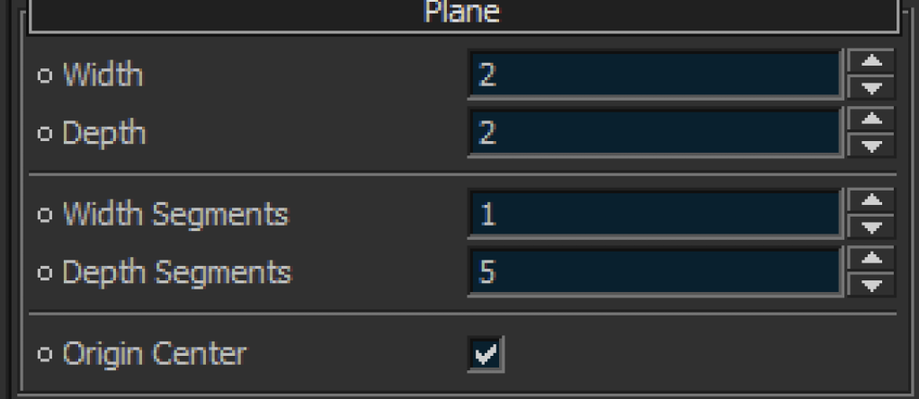
Make a plane and stretch it out
Go to the attributes manager and make 5 depth segments. Then press the top-left button to “Convert to an editable”.
 | 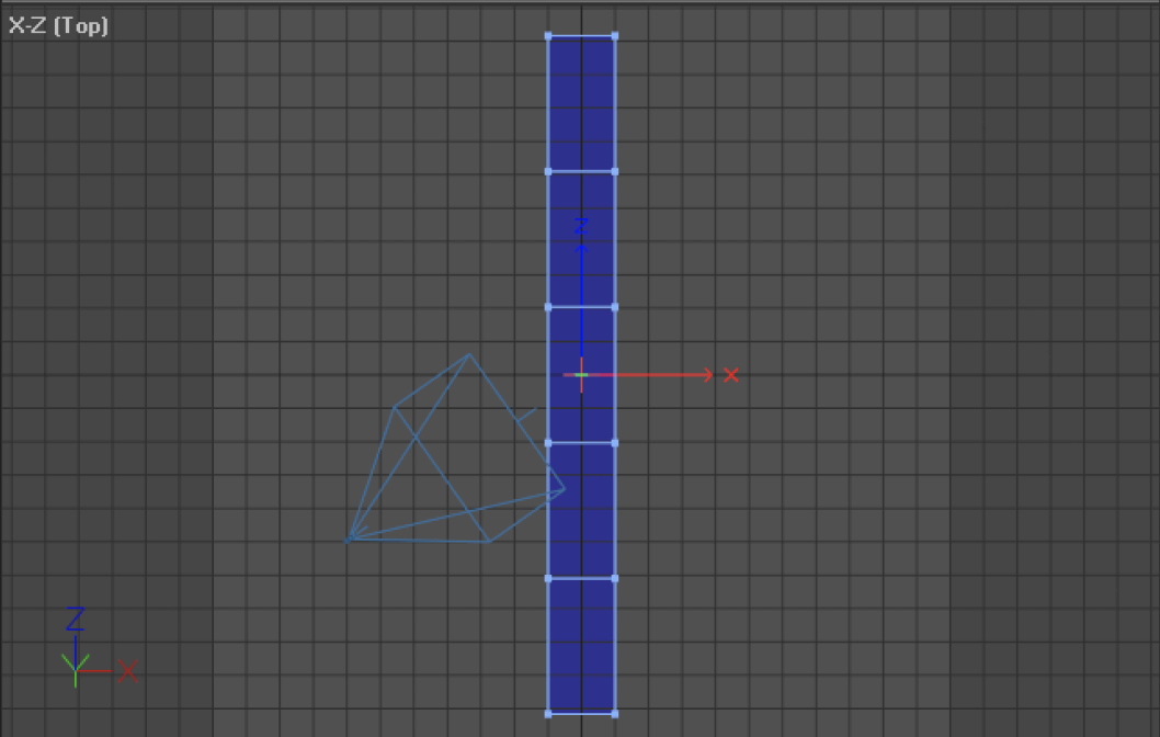 |
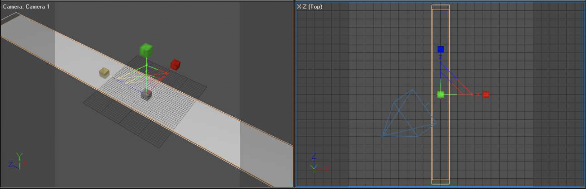
Click on the “Points mode” button and drag/select the middle points of the object one by one and drag them.
Attention you might notice when moving with the move tool, it’s very sensitive, that’s why I suggest you zoom in to the scene when moving.
Only move the Z-axis, you do this by clicking on the blue arrow and dragging when you have the move tool selected. Therefore you will be switching from the move tool to the select tool a few times. If done correctly it should look something like this.
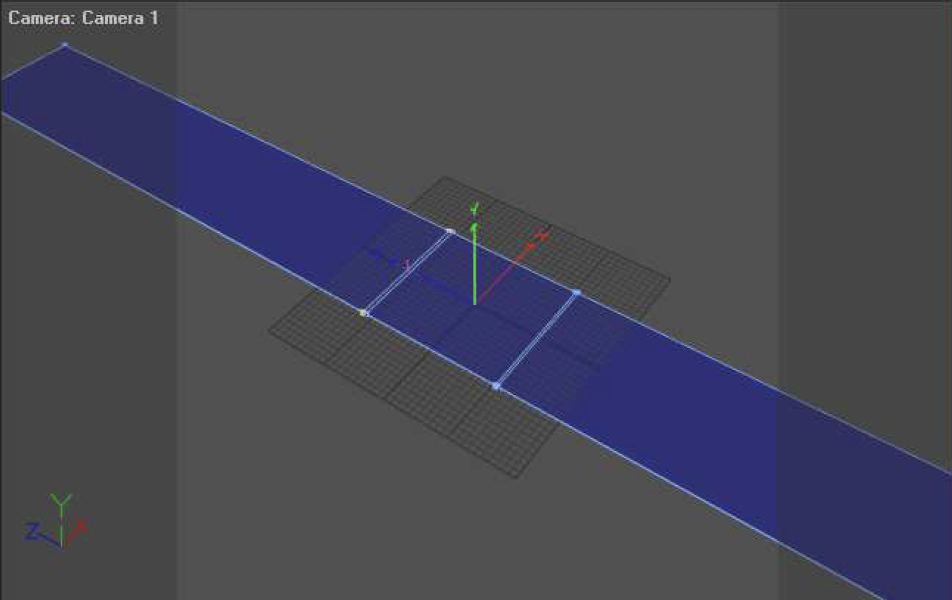 | 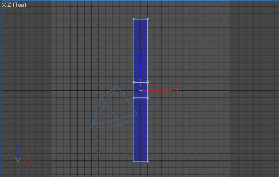 |
Now go to edges mode and select the following edges and drag out according to the pictures below.
 | 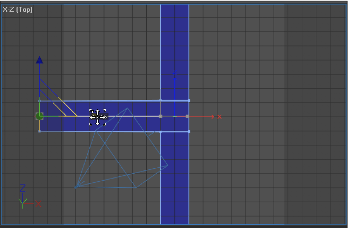 |
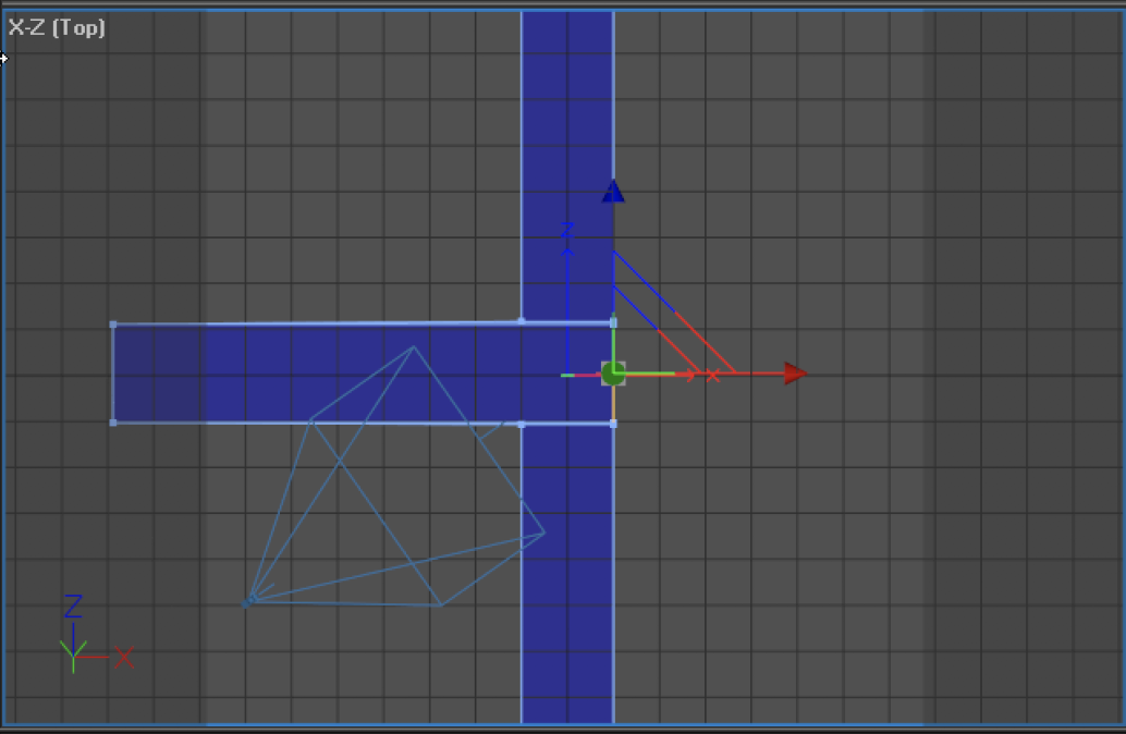 | 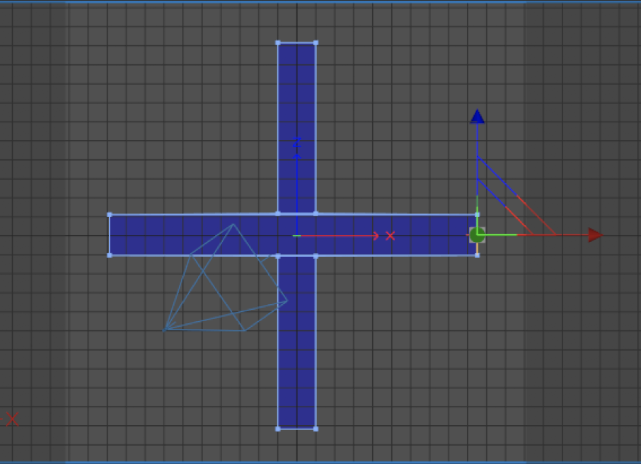 |
The road is done!
Now click on the “Objects mode” button.
There’s one more thing that needs to be done before we can start placing buildings (which, in our case will actually be different sized cubes).
Make a plane by clicking on the PLANE button. Then click on the “Scale” button and increase the size of the plane you just created, by clicking and dragging the middle of the size tool seen in the viewport.
After that, click on the “Move” button, and move the plane downward a little, so that it is beneath the road.
 | 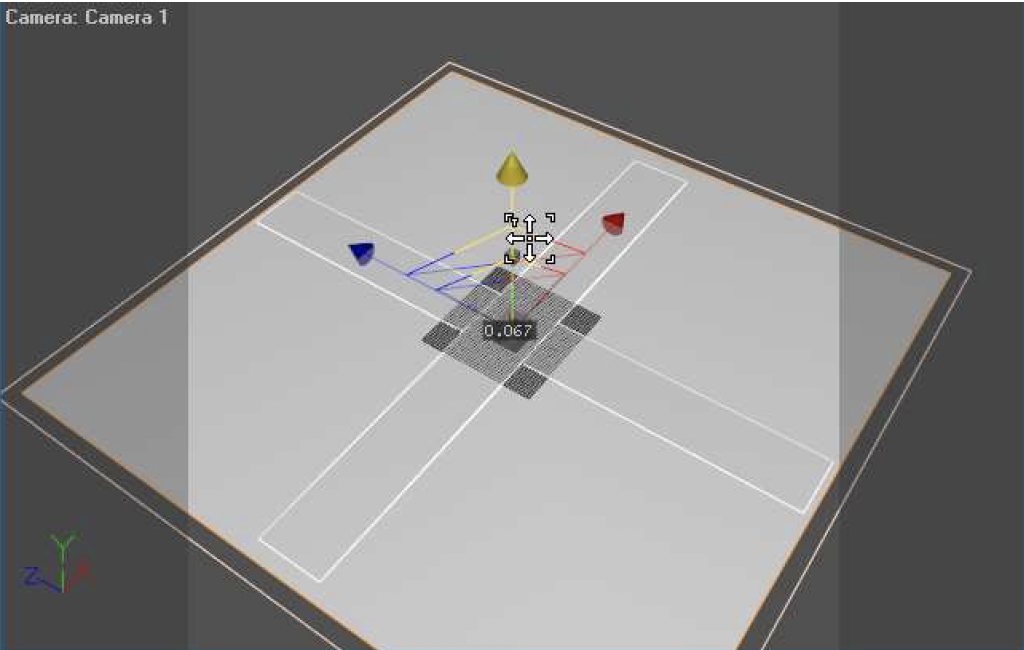 |
Now we’re almost done so that we can place buildings!
Go to the attributes Manager and scroll down to the Laser tab. (Make sure the plane is still selected. From here you reveal the “Line Types” tab and check the box: “Custom Line Types” Now make sure it looks like this:
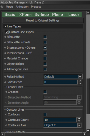
By checking and unchecking the boxes as we have above, we’ve told BEYOND 3D that we only want to see lines that intersect the plane (if other objects also allow this) and that we don’t want to see any other lines for the plane (such as the periphery of the plane itself). We made this selection because – in this case, we are only using the plan to “hide” the bottom of the buildings.
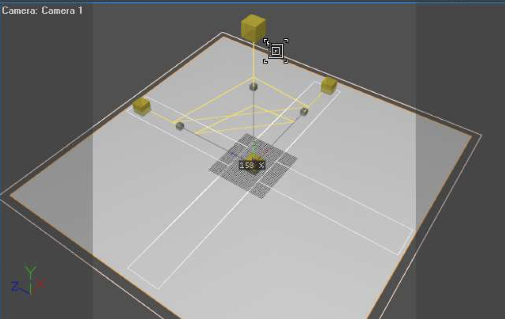
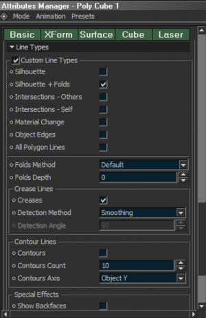
Now place a cube by clicking on the “Cube” button, and size it a bit using the “Scale” tool. Then – as we did above, go into the laser settings and uncheck: “Intersections – Others”. This will prevent the cube from placing lines on the bottom of the plane we just placed in the scene and cuts down on flicker.
Now create more cubes using the cube tool, or simply copy the existing cube, changing the size each time you create a new cube, and placing the new cube somewhere else.
You should have something like this now:
Back in the day before 3D animation, every frame of an animation needed to be hand drawn frame by frame. A set of frames had to be created to make an animation. This was very time-consuming and tedious.
BEYOND 3D provides benefits over this old-school drawing method, in that you can produce a set of frames (an animation) much quicker than anybody could draw them by hand.
3D animation depends on items called “key-frames”. These key-frames are like a snapshot of a certain look at a certain time. If you have two key-frames (snapshots), then you can change the scene in some way. For example, each key-frame can change the size, position, rotation, color, or all of this at the same time.
In 3D animation, it’s usually expected that you skip a few frames for the next movement, the computer interpolates between these key-frames and creates the frames in between, in other words, during the interpolation the 3D software kind of morphs to the next key-frame.
The interpolation determines how dynamic something moves, will it speed up at the end or will it slow down.
Here you can see the interpolation in the BEYOND 3D animation editor.
Notice the curve you can see the object first speeds up then slows down again. (More on interpolation and how to adjust it in a moment.)
To animate in BEYOND 3D you need to be in the Animating layout. You can get there by clicking on the drop down list box with the orange background, in the middle top of the screen.
Before switching to the Animating layout please create a box first for this demonstration to work.
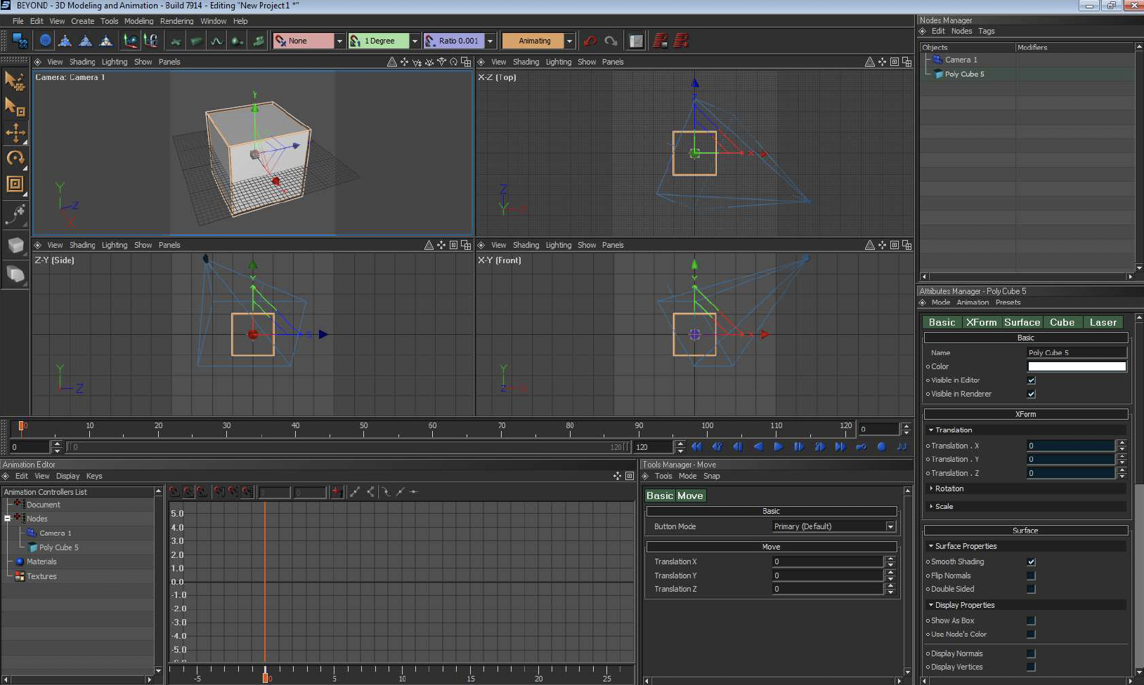
Having the box selected and being at frame 1 on the timeline.
Press the record button
![]()
A keyframe will be create on the timeline:
![]()
Now drag the time slider to frame 50 in the timeline.
Next change the position and rotation of the cube a bit, using the Position and Rotation tools. After that, press the record button again to record a new key-frame.
Now press the play button and Congratulations! You’ve just made your first 3D animation.
In the introduction I explained what interpolation is and how it works, now I’m going to show how to adjust the interpolation and how to work with the Animation Editor.
First off you need to know how to extend the size of the Animation Editorse curve view. You can do this by holding ALT and then dragging to your left or right. Drag up and down to see very tall curves.
The following example can be found in the file: Democube.beyond3d
I’ve made a loop by first registering the starting point with record, then going to the last frame without doing anything to the cube and also pressing record. At frame 25 (the middle) I have moved the cube a bit and recorded that. As you can see the curve shows you the how the interpolation of the movement go’s
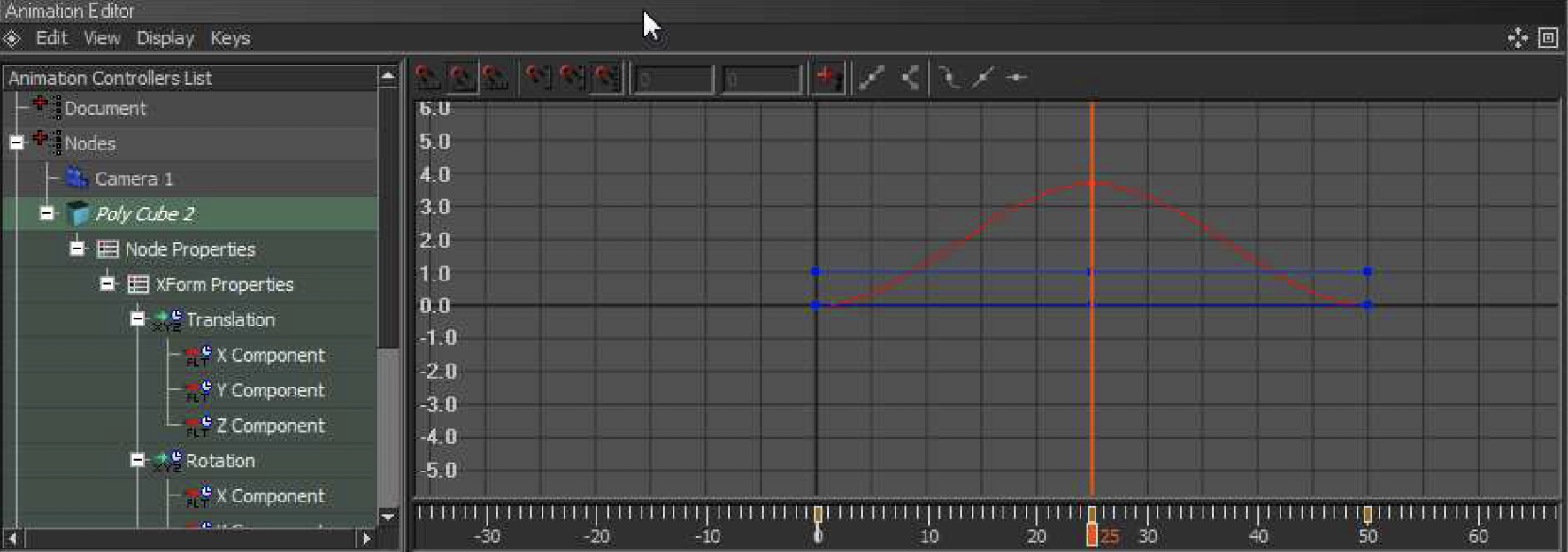
We are now going to change the interpolation.
Click on the top point from the curve.

You should see 2 blue dots next to the curve.
The left one determines the ending speed of the previous key-frame and the right one determines the starting speed to the next keyframe.
The point can be pulled closer the point where they come from for a more linear movement, they can also be pulled further from the movement to increase dynamics.
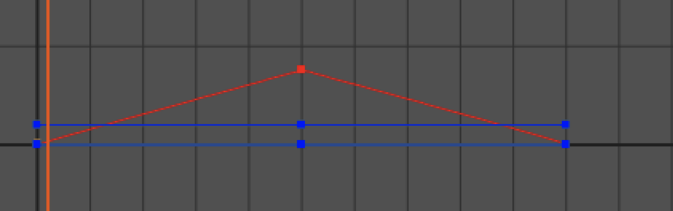
A linear movement should look like this:
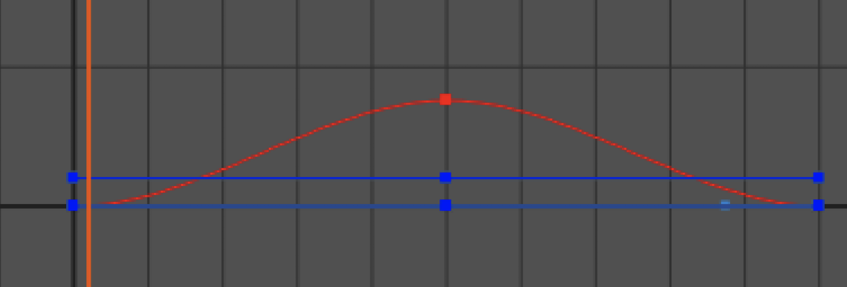
A (proper) dynamic movement should look like this (this interpolation is done by default):
If your moving out the blue interpolation points too far you get a movement that first go’s further then the main interpolation point, then sweeps back and the same for the next point:
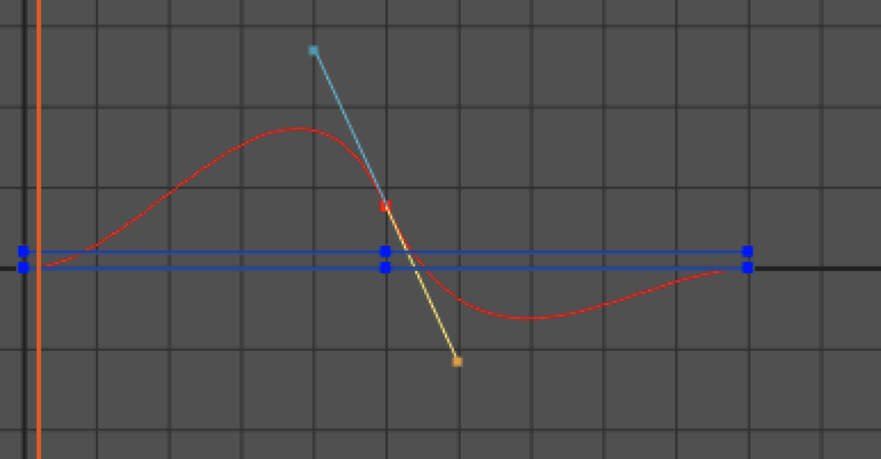
This should often not be used and in most of the situations a curve like this is not wanted.
Try fiddling around with the interpolation to increase the realism or dynamics of an 3D animation. Remember each direction of movement, rotation and scaling has it’s own curve and color curve.
Certain types of animation require you to reposition the pivot point.
What is a pivot point?
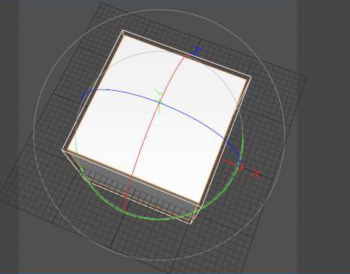
A is the point where all the tools have their center in, that center is it’s pivot. The center of this the rotation tool here is the pivot point.
The pivot point can’t just be moved, it needs to be done by adding an object to a group and then offseting that object from within the group. Now lets quickly make a door to show you how to do this. We make a door by flattening the cube and Stretching it out a bit on the Z-axis.
We Click the Objects Manager and either right-click in it and Choose: “Create new Group” or Press the N key. You will now have this in the Objects manager:
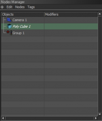
Click Poly Cube 1 and hold and drag it to Group 1. You will now have this:
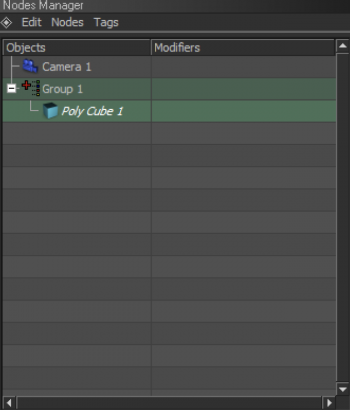
Click Poly cube 1 again and move it so it’s side just touches the center of the grid. Like this:
 |  |
Now click Group 1, you will see the move tool or any other tool will be in the center now. That’s because by default the move tool will be in the center *unless you start moving the whole group. Select the Rotate tool and rotate it 90 degrees so it’s standing straight up instead of laying down. Now if you move the horizontal part of the rotate tool, you notice it can sway like a door. If you want a door knob you can make some standard objects and drag those on the door just like you did when offsetting the door.
The result can be seen in the file Door.beyond3d
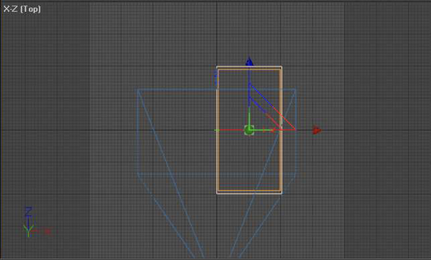
Camera animation requires you to have 2 camera’s in your scene. One camera is for the user to be able to navigate the camera through the perspective view. The other camera is for animating.
You can *but it’s not required* Set one of the 4 views to camera 2 so you properly see what the camera your animating is seeing. I’ve chosen to sacrifice the Front view because I will be using the side and top view to position my camera. Like this:

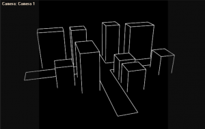
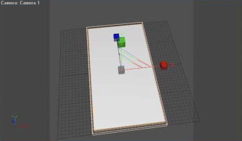
I will be using the City.beyond3D scene for the camera animation tutorial.
Before animating the camera go to your render setup and in the renderer tab next to Camera/Viewport Set it to Camera 2 instead of Camera 1.
Now Start off with dragging the camera all the way back. So you see the city properly, I chose to raise the camera a bit above the city and tilt the camera a bit down with the rotate tool.
Remember use camera 1 to navigate and not camera 2
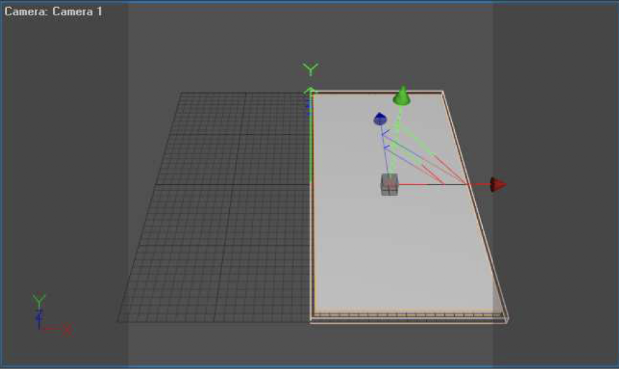
When your satisfied with what camera 2 sees then go to the animation layout and press the record button. For me the view looks like this:

Now go back to the standard layout and move to frame 70 and reposition the camera.
Do not play the animation before recording the position, if you do the camera position will be lost.
I’ve positioned it like this:

Now record that camera position too and play back the animation and see if it moves like desired.
We’ll see that it moves way to fast. 70 frames is not that much. So lets increase the total amount of frames too so we can move the keyframe further. We set increase the total amount of frames to 150

As you can see the scale is weird, we want to change that so we can see all frames in the timeline. To do that drag out the horizontal scrollbar.
To drag out click the ridged part of the bar where it says 40 in the above image and drag it out to your right side. Now the bar will show all total frames.

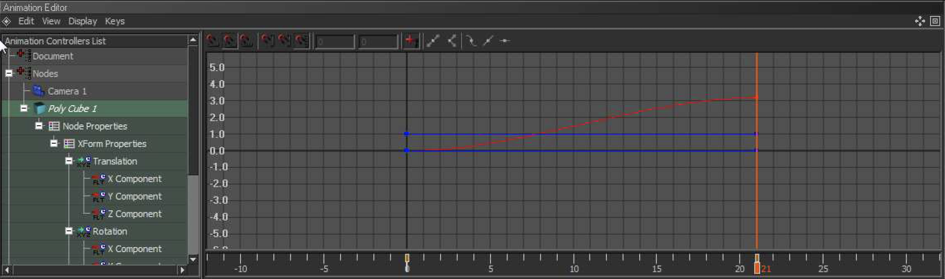
Now go to the animation layout, we need to move the keyframe to frame 150 To do this we use the Animation Editor. In the Animation Controler List we select Camera 2 and make sure we can see frame 70 till 150.

Now grab each colored ending dot and drag it till the key time says your at frame 150 (make sure you do not move up or down, try to move as horizontal as possible). If you happen to have it moved up or down a bit (which is likely) you need to go to frame 150 and reposition the camera a bit.
This is the key time:

*do this for each colored line (red it not needed in this case)
These 3 green lines only are for the movement in the X, Y and Z axis *colored the same color as they axis color. To also readust the rotation to frame 150 you need to click rotation and also drag that to frame 150.

The result of this tutorial can be found in file: City(WithCameraAnimation).beyond3d