
Tools
Support
Pangolin Family of websites
Pangolin Laser Systems, Inc.
Kvant Lasers
Unity Lasers
ScannerMAX
Lasorb
Tools
Support
Pangolin Family of websites
Pangolin Laser Systems, Inc.
Kvant Lasers
Unity Lasers
ScannerMAX
Lasorb
This allows you to set the line types on an object-by-object basis.

The Selection checkbox assigns the settings to a specified selection tag (e.g. fold selection). By activating this checkbox, the Edge selection checkbox and the selection name field will be activated, and some parameters, not necessary for selection assignment, are deactivated. The selection is specified with its name in the name text field.
To assign line types, first allocate the LC4D object tag to the specified object that you want to modify. Then click the check boxes to specify which line type you want (silhouette, creases, contours, etc.) for that object. These settings will be assigned automatically.
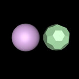
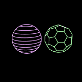
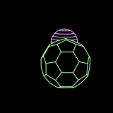
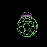
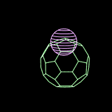
For example, let's say that you have two shapes: a sphere and a soccer ball (picture 1 below).
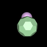
Therefore, for these particular objects, it is best to select the Silhouette and Contours line types for the sphere, and the Edge Selection line type for the soccer ball (picture 5).
 | 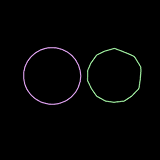 | 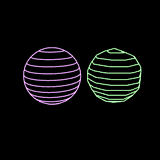 |
| 1: Original shaded objects | 2: Default line types | 3: Silhouette and Contours |
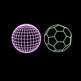 |  |
| 4: Edge Selection | 5: Silhouette and Contours for the sphere, Edge Selection for the soccer ball |
For the Contour line type, you can specify the contour axis. This is discussed in detail on the Contour axis topic page.
The Lasershow Converter 4D has the capability to create lines where multiple objects intersect. But what object is used to determine the color of the intersecting lines?
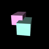 |  |  |
| Original shaded objects | Cyan cube determines color of intersecting line | Magenta cube determines color of intersecting line |
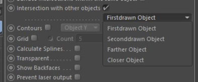
By default, Lasershow Converter 4D will favor the color of the object drawn first. However, you can control this on an object-by-object basis using the Color of intersecting lines drop-down list. The options available in this list are:
When you create objects in Cinema 4D, these objects are usually built up from standard types of objects like spheres, cylinders, etc. If the first object that you create is a sphere and the second object you create is a cylinder, the sphere is the “object created before” the cylinder.
The actual object number is shown in the Lasershow Converter 4D Laser Preview panel. As you select different objects, you will see this object number updated.
The main point to understand is that the object drawn first is the object that gets to choose what color the intersecting lines will be.
===== Why not always use the “Color of the closer object” as the color of intersecting lines by default?
Although this might work for some scenes, it might allow the colors to change in ways that are not obvious at first. Complex camera motions can make it so that an object that is closer on one frame, is not the same object that is closer on another frame. This can make the colors of intersecting lines change from frame to frame, which can be disturbing.
Most of the time, you should select either Color of this object or Color of object drawn later. Selecting one of these will ensure that no matter what happens, the color of intersecting lines will always be consistent.
In addition to the standard line types, there are three other line types available in this panel. These give you more control over the objects being rendered and allow special effects.
 |  |  |
| Original shaded objects | Show backfaces and Transparency disabled | Soccer ball with Show backfaces enabled |
 |
| Soccer ball with Transparency enabled |
Note that transparency and backfaces are two separate and different options. Making an object transparent does not allow you to see that object’s backfaces. Likewise, showing an object’s backfaces does not allow you to see through that object to other objects.