
Tools
Support
Pangolin Family of websites
Pangolin Laser Systems, Inc.
Kvant Lasers
Unity Lasers
ScannerMAX
Lasorb
Tools
Support
Pangolin Family of websites
Pangolin Laser Systems, Inc.
Kvant Lasers
Unity Lasers
ScannerMAX
Lasorb
Note: the kinetic lights plugin is a separate license and requires purchasing separately from BEYOND software. The plugin is available for purchase and can be added to any BEYOND software license level.
Pangolin development team received many questions and requests to help make effects where lasers track to kinetic fixtures, sometimes RGB balls, mirrors, or other surfaces, easier to work with and program Inside of BEYOND working with a lighting console like GrandMA2 or Madrix, over DMX or Artnet. Below were the goals.
Using these features, we allow BEYOND to control positions of laser content, act like the physical fixture, and control directly from a lighting desk to match the kinetic fixtures.
We will be covering each of these features in this manual to go over each, and give an insight to how they work and why they work the way they do, so you can get the most out of the plugin.
We have also produced videos going over this feature in depth in our deep dive, and as fast as possible in our quick hints videos. These can be found on YouTube, or our website.
Quick Targets Beam Settings
Kinetic tracking is located in Quick Targets Beam Settings, to access this menu, go to:
Settings > Quick Targets Beam Settings
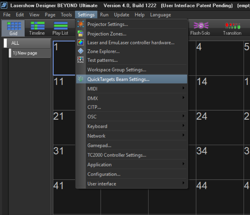
This opens the window “Quick Targets Beam Settings”, where the kinetic plugin features are located.
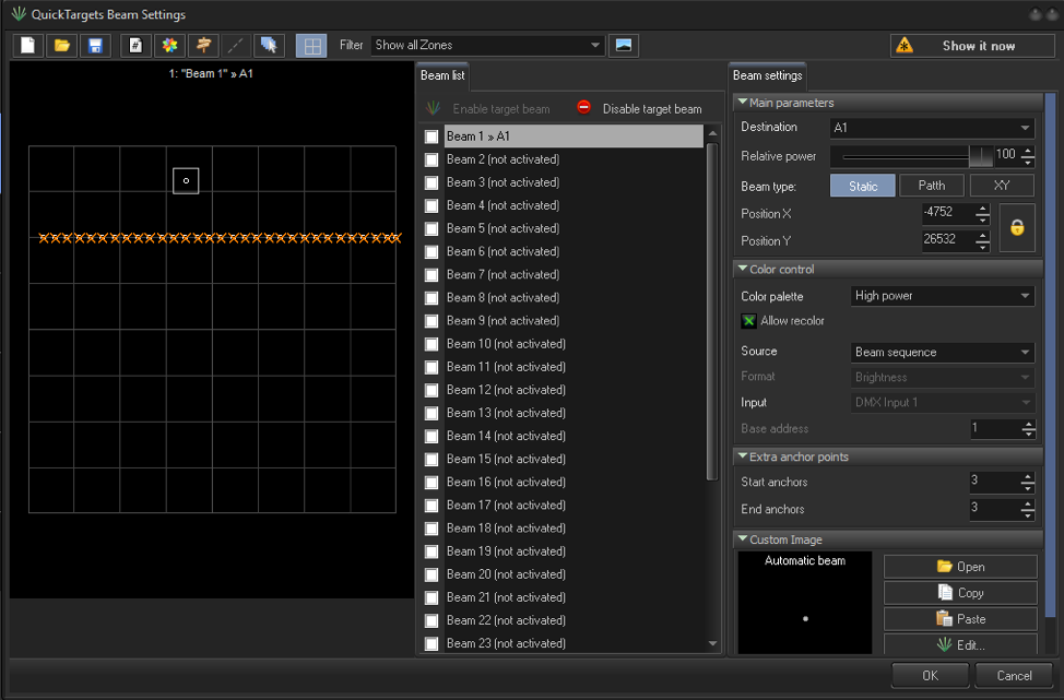
Here we have control of our beams, where we can set our destination (zone), its power, and if it Is enabled. These features work the same as they do normally In Quick Targets Beam Settings.
Start by selecting a beam; in this case Beam 1, and set its destination to the zone you wish, in this case “A1” Then select “path” to enable a beam path, (kinetic tracking) and this will change our menu to add path data.
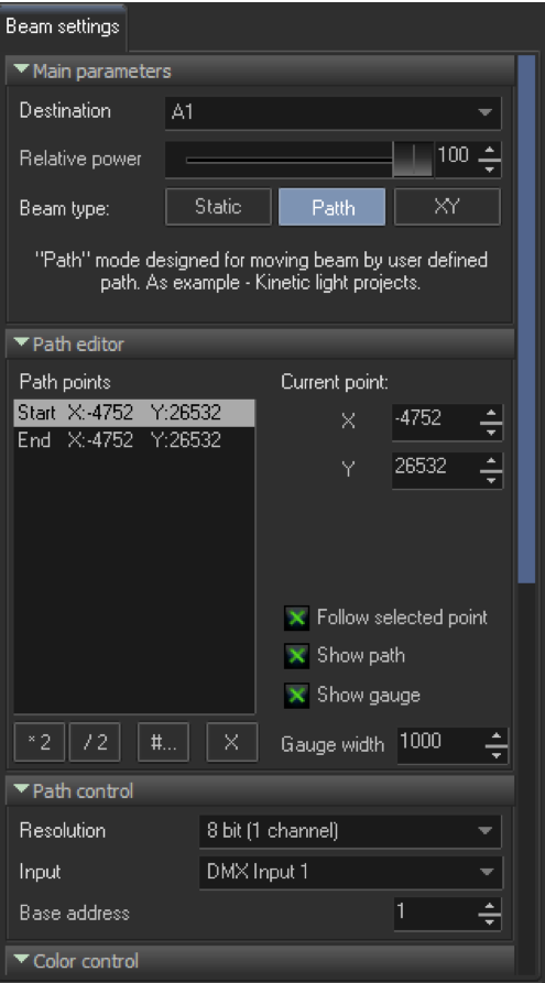
If we select our beam in the grid, we can move our start, or end points to create a path. In our “Path points” we can select either the start or end to then move the point with our mouse or keyboard. We can add points by multiplying to add resolution or you can add your own number of “path points”.
On your console, its best to put a specific kinetic fixture at its “0%” position and place your starting beam by moving it with your mouse, ensure “show it now” enabled. Position your beam onto the center of the ball, or whatever you are hitting. Then move your fixture to the “100%” position and do your end point.
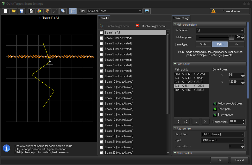
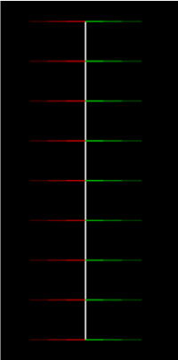
From here you can add points if you would like more resolution, by setting a midway point 50% and 1/2 respectively, or more by adding more sections. In the figure above, you can see we have 5 points positioned. In most cases your path will be straight, but if you introduce bounces, or complex kinetic setups your path may need many more points to be accurate. This can be done by clicking the following:
You also have options to assist you with your beam positioning: Follow selected point – display beam at position of selected point of the path. It required for setup. Otherwise, position of beam will be controlled by DMX.
These will make your output look like the image below.
This panel contains DMX related settings for beam position control from DMX.
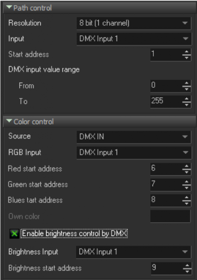
Beam color can be controlled in several ways Source parameter has 3 options:
Red start address, Green Start address, Blue start address represent DMX channels which will control corresponding beam color channels. Such model allows to define order of color channels as you need, or use one DMX channel for all 3 color channels, this will give simple brightness control. When all 3 color channels have value 0 then beam will be turned off (laser projector will not display it). For all 3 addresses 0 is minimum and 255 is maximum.
Enable brightness control by DMX - Some fixtures have separate brightness channel. In this case, BEYOND has optional brightness control channel. BEYOND uses RGB color representation by default.
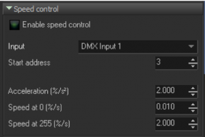
This is where we can adjust our beam movements, so the beam reacts more like a physical fixture instead of a digital position. Imagine you had a position in your programmer for your kinetics, if you clear your programmer, the balls take time to retract to their “start” position. While the DMX value instantly goes to zero. Since BEYOND is listening to DMX values directly the laser beams would return immediately to the “start” position set in the path.
In order to create physical movements, we have created an algorithm to create artificial physical movements to match kinetic fixtures.
The simple solution is to always leave your kinetic fixture at maximum speed and use the following equation to solve for your 3 values.
100/(DxS) = A
D being total motor distance (in meters) S being motor speed (in meters per second) A being “Acceleration (%/s^2)“ in BEYOND Set this value “A” for all values if you intend to not change motor speed
If you would like to use the motor speed control in the fixture, you can use the same equation for the slowest speed, and the fastest speed in order to use a speed channel for the fixture and for BEYOND to follow. Though this proves harder to find what the official rated speed of a fixture is at its slowest, while its much easier to find “Maximum meters per second” on a specification sheet for a fixture.
Following this equation (assuming the documentation from the manufacturer is correct) will line up perfectly to the motor, if it doesn’t, you shouldn’t be far off, and you can do some testing by lowering the value if the laser tracks to slow, and raising the value If your laser tracks to fast.
If your fixture has a non linear speed control values, this will likely not work, and it is recommended to not use the speed control, and leave it at maximum speed at all times, speed of effects will not be affected in this way, and you only need to know the maximum rated speed for the equation, making things simpler.
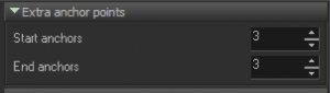
Each beam is considered as an independent frame, where path optimization controlled by Projector Settings (see Points between tracks). However, in some situations you may want to add extra blank anchor points surrounding the beam points. In such cases – set Start anchors and End anchors to value between 2 and 5, it should be enough for typical protectors.
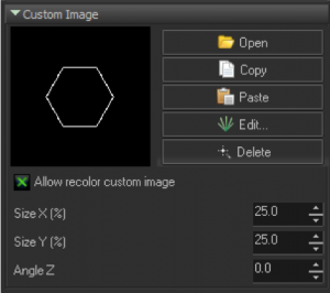
Quick Target system allow to use frame, and other images instead of just a beam. If you use custom image, then BEYOND will stop dynamic power distribution and each beam will take as much points as supposed to be in the Image.
Size and Angle parameters used to control size and angle of the custom image output.
Note: panels such as Extra anchor points and Custom Image are not actually related to Kinect light, and mentioned here for getting complete overview of beam settings.