
Tools
Support
Pangolin Family of websites
Pangolin Laser Systems, Inc.
Kvant Lasers
Unity Lasers
ScannerMAX
Lasorb
Tools
Support
Pangolin Family of websites
Pangolin Laser Systems, Inc.
Kvant Lasers
Unity Lasers
ScannerMAX
Lasorb
The BEYOND software controls a Laser projector through the use of Pangolin hardware such as a QM2000 or FB controller. BEYOND uses a hardware serial number for the identification of a Laser Projector when BEYOND loads or saves the projector settings. Positioning of a projector’s hardware controller in the list is not important, because BEYOND uses the serial number from within the BEYOND configuration file. BEYOND loads and saves Projector settings automatically.
If you need to change the order of projectors in the list then use the “Laser and EmuLaser controllers” menu.
The Order of projectors is important for Projection Zone settings. Projection zones do not use the serial number for ordering, it uses the number of Projectors in the list. Such as Projector 1, Projector 2 and so on. Such a model allows quick and easily ordering of the connected hardware controllers.
| Tool | Description |
|---|---|
| Open | opens Projector settings from a previously saved file. |
| Save | saves Projector settings to a file. |
| Copy | copies Projector settings to the clipboard. |
| Paste | pastes Projector settings from the clipboard. |
| Creator Serial | sets the LD2000 Security serial |
| Test pattern | calls a Test Pattern dialog box that may be required to set the scan area size, scan rate, color shift, and other projector settings. |

Size and Position are “global” settings of the Projector. “Global” means all Projection zones that go to this Projector will be influenced by this setting. The Projection Zone menu has Geometric correction settings which can appear to create some redundancy.
Some clients will set the Size to 100%, Position to center, and do XY corrections by means of the Geometric Correction settings in the Projection Zones Menu. Other clients will set the Size and Position, sample rate, and color shift by test patterns here, and then allocate all Projection Zones geometry within this tuned area. Each method has positive aspects.
There are 3 simple additional settings:
| Invert X | inverts X coordinate. |
| Invert Y | inverts Y coordinate. |
| Swap XZ | swap X and Y coordinates. |

Default sample rate values should be tuned using Test patterns. There is direct relation between default sample rate, color shift, Sample rate, Size, and Position. Bigger size means a larger angle and as a result more time is required for motion; your Sample rate should be lower. Conversely, for smaller angles, the sample rate can be higher.
Pay attention to the sliders below the Default sample rate, Minimum and Maximum. These sliders set the limit for the Default sample rate. This is a final limiter that works on the final preparation of the frames before they go to the hardware controllers for display. A high sample rate may damage the scanners in your projector. That is why there is a limiter. The sliders also control the Default sample rate slider. On the screenshot above, the maximum is set to 30K, bit this is not the real maximum.
Color/Blanking shift controls the delay of Color signals relative to the XY values. This setting only has positive values. If you experience “tails” off of your hot points or other content, this value may need to be adjusted.
Minimum number of points. This is a very important parameter. It may have effects for laser output power; it is important for CPU/USB/Network loads which can cause system overloading resulting in jittering, jerky laser output. Additionally there is a problem of “over power” for vector frames.
Wide Angle Compensation: Wide angle compensation is a new check box in your scan speed tab of projector settings which will automatically slow scan speeds down when projecting at large scan angles. This has the benefit of lowering the heat inside the scanners, correcting “bent” corners in projection, and extending the life of your scanners.
For using Wide Angle Compensation, you will set the scan speed at the rated scan speed of your scanners, and when you project at larger angles beyond 50% size, the compensation may come into play. It automatically determines parts of frames which may be difficult for the scanner and slows the scan speeds down ever so slightly to make the image correct at large sizes and remove heat from the scanner. The number of points this tool adds to frames is very minimal and often won’t be noticed so for most users its best to keep this enabled.
This tool has been tested on a wide variety of projectors and scanning systems including ultra-low cost scanners you may find in budget systems to high end Saturn scanners from Pangolin and ScannerMax like our Saturn 1 Series of scanners.
As an example situation, say you want a bottle of beer for a dinner. You get in your car, drive to the store, buy a bottle, and drive back. The next day, you have a party and you need a case of beer for dinner. Again, you get into your car, drive to the store, buy the case of beer, and drive back. The purpose of this example is to show, wether is it one bottle or a case, there is a specific amount of time being spent on the process of getting the beer. What is common to both situations? In both situations there was a time (calculation/resource) cost to get to the store and back where the number of beers purchased is irrelevant. The system load situation with computer data computation is similar to this example.
It is a common misconception for people to think making a frame with only a few frame points will help their control computer work more efficiently and therefore faster when actually the opposite is true. For example, if a frame is created that has only 10 points, and you have your projector scan rate set to 30K. 30K/10 = 3000 times per second that BEYOND will need to calculate this low point count frame, while also performing all its other related computations. If a frame has 100 points, then the computer will only need to calculate the frame 300 times. If the frame has 300 points then it will be calculated 100 times per second. There will be an obvious difference between calculating 3000 times and 100 times. High FPS values, as a rule, mean higher loads on a computer’s CPU because each calculation has a resource cost.
High FPS is not always possible to provide. For example, if you want 3000 FPS from a system, but the system is also trying to do some addition job (multiple resource intensive applications running at one time), or simply the system is not robust enough. What will occur is the Software will be unable to supply the calculated frames in the correct amount of time, and you will see problems with the laser output not being smooth and linear. The problem will cause poor visible output displayed from the laser projector. One more example for consideration, just using arbitrary numbers, you send 10 points, what approximately takes 100 bytes. The Ethernet packet will be at least 500 bytes. You are only sending 100 bytes, but the Ethernet communication layer is going to send 500, meaning you are only using 1/5 of your network’s speed, and 80% of that communication speed is lost. The main thing to keep in mind is that there are details related to buffering that should be considered when creating frames.
Minimum number of points in a frame for the FB3 hardware is 128 points; we recommend to set this value to 200 although sometimes it is helpful to have the value set to 500 or 700.
Now that we understand why low point count frames can be a problem (system overload, inability to deliver data on time, etc); this is why we default the minimum point count to 200. What occurs if we need to display a frame that has only 100 points? The Software adds an additional 100 blanked points to the frame. This means that for half of time it takes to draw the frame, the laser will be off, and half the energy will be emitted. What we be done about this? Decreasing the number of minimum points may cause unwanted consequences; a much better solution is to increase number of points within the laser content frame.
Vector frames and minimum point number. For vectors, BEYOND calculates the number of points dynamically, based on spacing. This allows BEYOND to keep the brightness of a line (vector) at a constant level when the line is calculated. If we have some minimum point number defined, then BEYOND will be able to compensate the for any brightness issues.

Use the dropdown to indicate the number of and type of lasers in your projector, and set the “color system type” using either TTL, Analog with linear responce or analog with log responce. Most users should use linear, or log for better low brightess resolution. BEYOND offers a few standard modes for quick setup and an Advanced mode that provides more flexible options.
Number and type of lasers - choose the number of lasers in your projector.
Advanced options can be used with up to 6 lasers.
Color system type - chose the modulation type that corresponds with the lasers within your projector.
Advanced options provide a customizable diagram for each laser.
Color output levels - sets the minimum and maximum voltage levels for color outputs.

The Advanced mode allows for 6 color channel setup. Its important to note that if your laser has more then RGB inside, you will need to go to Advanced mode to actually use the extra color channels.
In advanced you have the training colors on the left, and non linear correction on the right.
Training Colors - Here you can set your 6 color channels values for different hues, BEYOND will blend between set hue values for all other hues, you can also add hues using the plus button, and rename hues with the rename tool for hues not at every 30 hue values, as those are “set” colors. You select the hue you want to tune, and you can set the values used for each color channel to the right. it may be useful to use the “Medium colors test 2” to help train colors.
Nonlinear correction - This is to set the fade curve of your lasers in your system. Lasers that are linear in power will not be linear in apparent brightness, so we must adjust the line.
To do this, first use the “NewColorTest” or “4 circle” test pattern, and only look at one color at a time using “recolor test frame and cues” Each circle is one of the 4 dots that arent 0 on the 5 point mode on the graph. The goal is to adjust the 3 in the center until all 3 circles are the same brightness. Once that is done, change to the “Gray scale test” pattern and slowly bring the 0 point up until the last circle is just barely visable. From there switch to the “9 point” mode in the graph, and take the 0 value in the graph back to zero. You will see distint steps between each cirlce in the grayscale pattern.
If you do the line for each laser, you will have much better dark colors and pastel colors from your laser and your fades will be much smoother.
Add your tuning points to this and you can make almost any laser have a perfect color tune.

BEYOND generates special transitional (short) frames between the tracks/frames as well as between display updates. For example, if you display two cues, then BEYOND will inject a transitional path between them. The path is a blank line with a few anchor points in beginning and ending of the line.
Fixed point number - the path always has the same number of points distributed between the start and end points of the path.
Spacing - the number of points in the path is calculated dynamically according to the distance between the starting and ending points. If the distance is less than one space, BEYOND will not generate the transitional path.
Beginning anchors - number of blanked points (anchors) in the line beginning.
Ending anchors - number of blanked points (anchors) in the line ending.
Beam Generation Settings - minimum point number. BEYOND has a specially designed, power optimized system for beam generation used for Target Beam Sequences. The system is most effective when Target Beams is using static beams. BEYOND takes the minimum points as a basis and distributes them between the beams dynamically. The Number of points may be bigger than the minimum.

Visible lines spacing - the spacing (distance) between visible points. BEYOND measures spacing between two neighboring points and if the distance is 1.5 (or more) spaces, then BEYOND will add extra points in between. Number of points is a rounded value of (A-B)/Spacing.
Blanked lines spacing - the spacing (distance) between blanked points. As a rule, the spacing for blanked lines can be several times more than that of visible lines. Two big of spacing can be dangerous for your scanners because of peak voltage and consequential overheating issues caused by this.
Use nonlinear spacing for blanked lines - nonlinear spacing places more points near the beginning and ending of a line and a bigger distance between points in the center of a blanked line. As a rule, this option works better for blanked lines.
As a rule, a frame is a sequence of multiple visible vectors/points and blank line(s) in between. The place where a blanked line becomes visible, or a visible line turns to a blanked line requires additional anchor points for vectors.
When a visible line turns to a blanked line (end of visible line), BEYOND adds a few visible anchor points and a few blanked anchors after the line gets blanked. A similar process happens when a blanked line ends and starts a visible line. Here a few blanked and visible anchors should be added. Such points are never added between visible lines or between blanked lines (for this we have Angle optimization.).
Visible line begin - anchors at the visible line beginning.
Visible line end - anchors at the visible line ending.
Blanked line begin - anchors at the blanked line beginning, works together with “Visible line end”.
Blanked line end - anchors at the blanked line ending, works together with “Visible line begin”.
Angle optimization works for visible lines only and between visible lines only. If there is transition between a visible and blanked line, BEYOND adds anchors according to the Anchors section.
Linear angle to anchor relation - number of anchor points in a 180 degree turn.
Custom Setting - a diagram that allows setting the number of anchor points for turns of 100, 40, 60… 180 degrees.

EmuLaser has very simple configuration settings.
Enable Line Smoothing - Tis will smooth lines in output instead of going point to point, similar to scanner simulation but more just interpellation between long distance points.
Width - this will be the width of the line in output, larger lines will be brighter but look less like a laser line in video, smaller lines will look more like a laser but not be as bright.

We have added a tab on the projector settings window for projectors which feature Beam Brush®. As there Is control parameters that need to be considered with a Beam Brush® projector. This tab Is exclusive to each connected piece of output hardware and is saved to the pc and can be saved to a file for future loading.
Even though all efforts are made in manufacturing to keep everything lined up perfectly and corrected, the reality of touring means things can get bumped and shifted, so to compensate we have added multiple features so you can correct and get the best performance from your Beam Brush® even after months of touring on the road, without having to open the projector to realign.
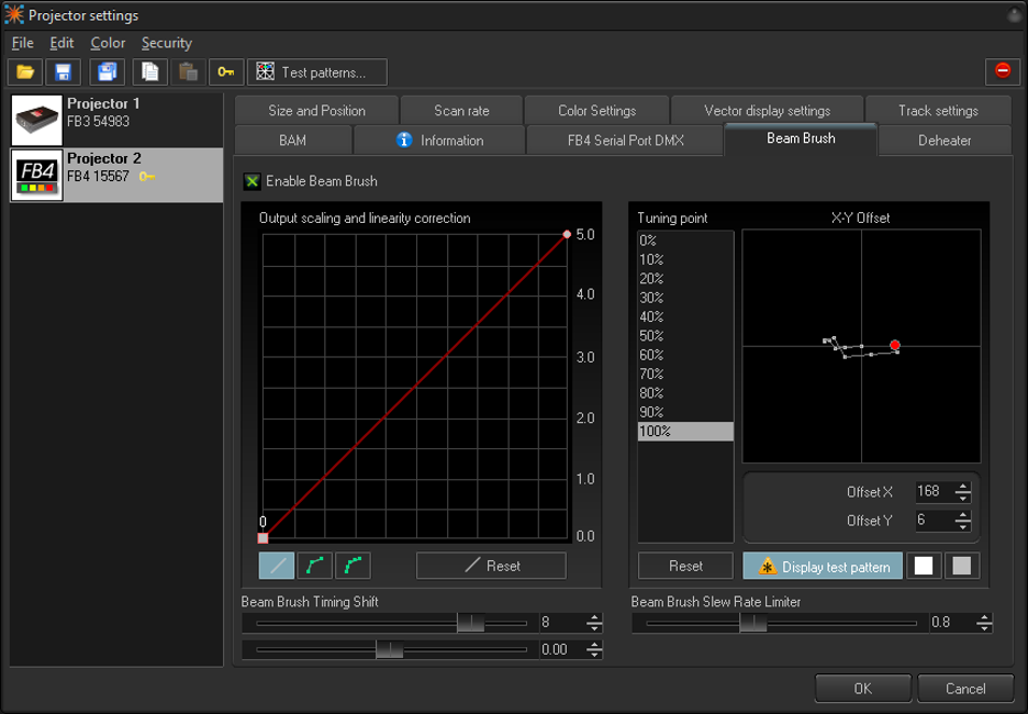
Output Scaling and Linearity Correction
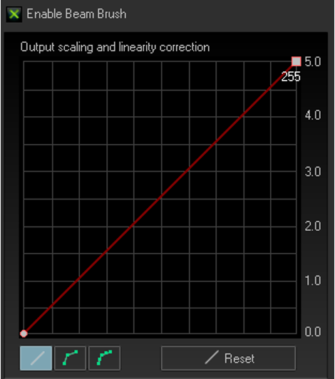
In Output Scaling and Linearity Correction we set a minimum and maximum brush size. Generally, this would be 0 and 255. The minimum can be used to set nominal If zero is no longer zero. While this is unlikely its not impossible. We can then use the maximum to set the maximum brush size on the projector. For most beamshow applications this should be at maximum. However, some long throw graphics projections may not want to use full brush size as it will be just blown out if the x/y scaling Is significantly different (in terms of projection size. Its recommended when programming to use full range, so on site the whole show can be rescaled down instead of needing more and there being no more left.
It is unlikely that this output scale would need a curve, as the brush mechanism is linear. However, we have added the option to curve your output scaling if needed. This works just like the advanced color correction curves.
X-Y Offset
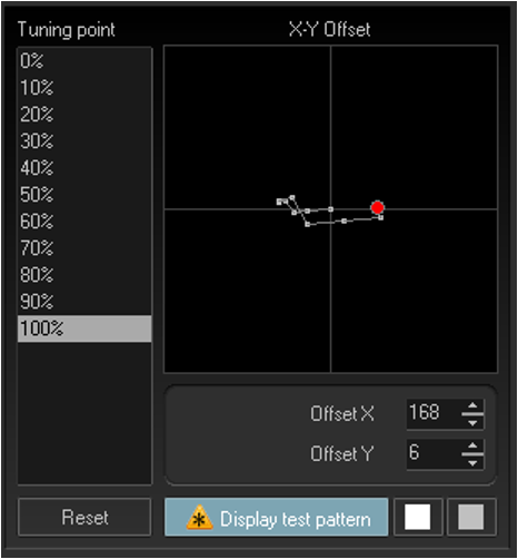
Beam Brush® systems as they move through brush values will create a slight X-Y shift in output. This can be minimized with perfect alignment, but in the reality of the touring world, this is unachievable, so we have added a X-Y compensation to tune this shift and make your output perfectly smooth. This X-Y offset is done before the output scaling and Linearity correction This means that it counts for the full 100% of the potential brush range. So, scaling afterwards will not affect X-Y Offset.
On the left you have percentage of beam brush value, and on the right, you have those points for their X-Y shift shown in a grid. To align use the test pattern to display the X-Y shift pattern, this will show a non-brushed square and a second square with the percentage of Beam Brush® selected. Scroll through the different percentages and use your mouse, or the value enter area to move the centerline for the brush. If you need to go beyond the visible graph, you can use the number input areas below the graph and increase the values further, beyond the visible graph.
You can adjust the colors for the test pattern using the two squares to the right of the display test pattern button. The first is for the non-brushed center, and the second is the color of the brushed square. This Is easier to display in video so check out our quick hints video on Beam Brush™ settings to see how to do this offset alignment.
Beam Brush® Timing Shift and Slew Rate Limiter
For timing and shift compensation, we first have Beam Brush® timing shift, this is like color shift and changes how early the instructions sent to the Beam Brush® mechanism compared to x/y scanner position and color timing, as they all react at different rates. 4 is a good default shift for 3mm systems, up to 10 watts, and 6 is a good default shift for 5mm systems, from 10w to 40w.
The Slew rate limiter is a calculation that BEYOND makes to make sudden transitions between brush sizes actually look like a sudden change in real life, as the Beam Brush® mechanism is driven by a scanner it does take (while very small) time to change positions. A slew rate of 1.0 should work for the default maximum brushed size that came shipped with your projector, however if you have changed the minimum and maximum size of the brush from a hardware standpoint with tuning, you may need to adjust this, lower number for less overall brush, and higher for higher overall brush.


Some Kvant lasers may have built in remote dichroic mirror adjustments. When the projector has this functionality the “KVANT Dichro” tab will appear. The first step will be to click “Read Status” on the bottom left, this will read the data from the projector on which “module” is doing what inside the projector. In the above example you can see Module 0 moves Blue to Red. You can use the buttons for left right up and down to shift the mirrors to do a color convergence in the projector.
Note: These directional buttons assume you are looking from behind the laser at it projecting on the wall.
Click on the arrow to go one step, do not click and hold these buttons, it will only move one step. You can adjust the “adjustment Parameters” below to change the strength of each click of the directional buttons where speed is how fast it moves on click, and time being the step size. Defaults for these are usually sufficient for most people.

FB4's have a serial port output on them, projector manufacturers may use this serial port to output data inside the projector, or even through the FB4 dmx output (if wired). This allows you to control internal systems like grating wheels and drop in filters, or output a dmx stream from the FB4. If wired, you can add “serial_mode=4” to the INI file to use it as a dmx output node, however it will no longer function as a DMX in, only output.

The info tab will give you information about the hardware, including firmware information, date of birth information (Date of manufacture), resolutions, mac addresses and more. You can also name your hardware here and it will be named throughout the software with that name.

The Beam Attenuation Map allows you to control the brightness of a laser projector over the entire projection zone that it will correspond to, and it also allows non-uniform brightness maps. You can see a quick tutorial video about the BAM here: https://youtu.be/JQnQYPq5WzU?t=178
The Beam Attenuation Map is a 64 by 64 “pixel” brightness control map. Each pixel can be set to any brightness level from 0 to 100%. Rudimentary tools are provided to sample a brightness level in the map, fill the entire map with the selected brightness level, fill a rectangular area with the selected brightness level and freehand-draw brightness levels into the map. Additional tools allow you to draw a gradient level of attenuation so the brightness of the BAM varies between two different attenuation levels.

Once you set a BAM for one zone you can copy these BAM settings to be applied to multiple other zones and have a bitmap screen shot of your drawn BAM copied to the clipboard, to be pasted into a document for possible use in a Laser Projector Product Report.
The Beam Attenuation Map can be used for graphics, atmospheric and beam effects.
Below is an example of a Beam Attenuation Map used for laser graphics.
One common use for the BAM, as it related to graphics, would be to prevent scanning above or below a certain point. For example, lets say that you were projecting laser graphics over a standard television screen with a 4:3 aspect ratio. Since the laser typically has a 1:1 aspect ratio, this would mean that the graphics could possibly scan above the top or below the bottom of the screen. You can use the Beam Attenuation Map to make sure that the brightness at the top and bottom of the screen are zero. Similarly, the window-clipping action can be done by means of the Effect tab.

Example Beam Attenuation Map used for audience scanning
Another common use would be to reduce the brightness below the horizon to a level that would be more pleasing for people in an audience scanning area. This can easily be done by selecting a reduced brightness level, and filling the rectangular area below the horizon.
Example Beam Attenuation Map use with targeted beam effects
Another common use would be to protect certain areas from hazardous laser exposure or to reduce the brightness in certain areas. When doing beam shows outdoors, it is often necessary to ensure certain areas (such as the windows in certain buildings) won’t be exposed. Using the rudimentary drawing tools, it is possible to “carve out” areas from the projected area.
Tools to create your BAM
There are a few tools included to create your map
Extra Options in gradients
Laser Cursor
To assist you figure out which pixel to color, you can enable a laser cursor which will project a scanned square where the pixel is to identify the correct spot to color. You can control the brightness of your cursor, and apply your bam to cursor to ensure that the cursor doesn't override.