
Tools
Support
Pangolin Family of websites
Pangolin Laser Systems, Inc.
Kvant Lasers
Unity Lasers
ScannerMAX
Lasorb
Tools
Support
Pangolin Family of websites
Pangolin Laser Systems, Inc.
Kvant Lasers
Unity Lasers
ScannerMAX
Lasorb
The scanners in a Laser Projector transform the incoming Laser Frame via a digital filter. Let's call it as good, or expected modification of signal. At the same time, due to various reasons, scanner or amps may have some quality problems that also influence the Output. Let’s call this an unexpected, or bad modification of the signal. Here, we don’t have any wish to discuss exact models, or products, only the main point - we live in a real world. Some scanners work great, some so well. Same story everywhere – cars, speakers, projectors, guitars, and so on. We should take it as fact, and understand – the scanner should carry out some transformation of the signal, but may do something else less desirable as well. BEYOND uses the math model of a “good” scanner, and applies transformations that the scanner is supposed to do. BEYOND does not do anything else. If a simulated picture looks different to the picture projected by your projector – yes, this is possible, it is the real world, and your scanners interpretation of the signal might not be as good as it should be. The problem here is your scanners. We leave aside any detailed discussion about the reasons, or what may go wrong.
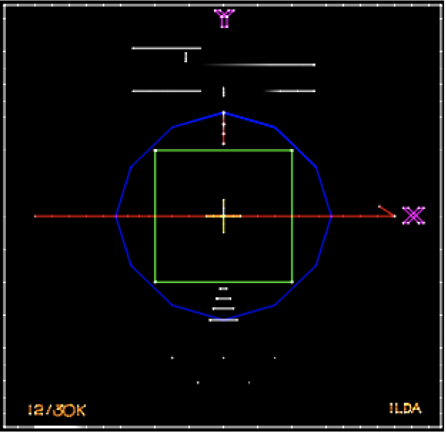
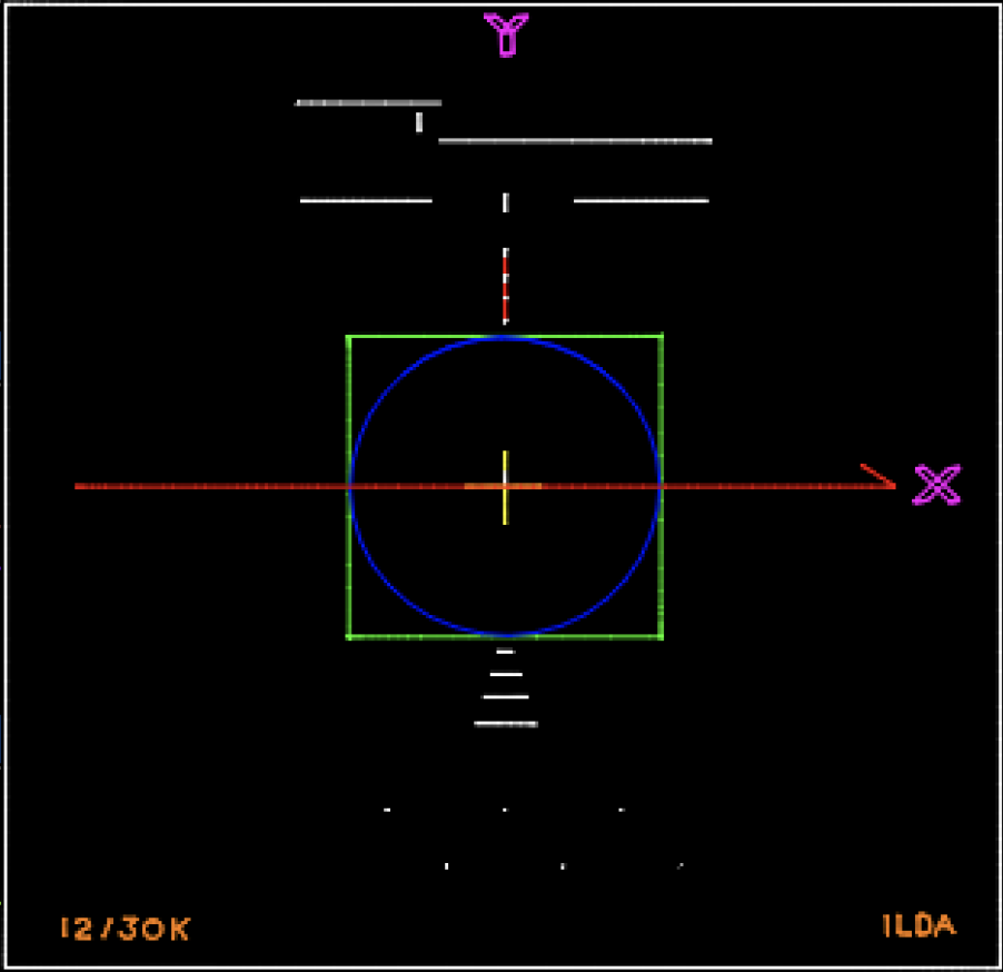
The ILDA Test Pattern is a great way to test the tuning of your projector. We can take ILDA test frames, see how the simulator works, and ensure that we can believe in the result. After that we can take some art work and compare the result.
About the expected modifications of the signal that the projector supposed to do. Pay attention to the blue circle in the pictures below. At the left side you can see the ILDA test pattern as it drawn. Open it in the Frame Editor, and check out the point placement. On the right side, you can see the simulated Output, and this is how the frame is supposed to look on Output. The blue circle must be a circle and perfectly fit into the green square. If circle is bigger or smaller, looks like an ellipse - then there is a problem with the tuning.
 |  |
This is what I meant above. The blue line is the simplest demonstration of an expected transformation of the signal that the scanner should apply.