
Tools
Support
Pangolin Family of websites
Pangolin Laser Systems, Inc.
Kvant Lasers
Unity Lasers
ScannerMAX
Lasorb
Tools
Support
Pangolin Family of websites
Pangolin Laser Systems, Inc.
Kvant Lasers
Unity Lasers
ScannerMAX
Lasorb
The Shape image in BEYOND is simple and flexible to construct; it is composed of two elements - a base shape and the effects applied to the shape. The base shape includes a few simple wave forms, audio driven forms, and a recorder (FIFO). The Effects include the full palette of BEYOND effects plus a few, specific elements for the Shape image - Single axis Oscillator, XY Oscillators, and Modulators. Such construction is almost opposite to the Classic LD2000 Abstract Generator and Abstraction because the Shape Editor does not include oscillator banks. Instead, you can add oscillators and modulators when you need them and the number that your need, to mix with various effects.

New - creates a new Shape.
Open - opens a Shape from a previously saved file.
Save - saves a Shape to a file.
Properties - see Image Properties dialog.
Tools - see below.
Yellow Tag - assigns an Identifier for a Shape. This transforms the Shape into a 1st level object.
Heart - add created Shape to a list of favorite Shapes for future access.
Monitor - paints the Shape by means of ERP (Enhanced Reality Preview).
Quad - shows a coordinate system grid.
Master - paints by means of LD2000 style - according the setting of the Projection Zones.
The Tools menu has a few advanced settings that provide the ability to fine tune the way points are generated within a Shape image. There are multiple factors that influence the final beam path of a Shape Image. There is the “Point between tracks” block that injects a transitional path. It may be an optional setting, but if it is not selected, a point could park the beam and create unwanted aberrations within the projected image. For example, if a circle is drawn, a hot point or gap could be created at the start/end position of the shape.
The other side is the generated frame. The Shape generates Vector data by putting anchor points at the start and the end of the path. In many cases we need to add anchors, but if we want a circle, then anchor points and transitional paths are factors that can be easily overlooked. Another overlooked factor is the first point being drawn. As a rule, in all cases, the first point is blanked (or black). This is normal, but if want a solid circle, and we start drawing it with a blanked point, a small gap will be visible in the drawn circle where the beam path starts/stops. One of classic solution to this is overlapping, a technique used frequently in the LD2000 circle tool.
BEYOND offers a few tools to control the frame generation more acutely:
Mark First and Last point as not-vector - the boundary points are not vectors, which means that BEYOND will not add anchor points.
Mark all internal points as not-vector - marks all points inside the frame as not vectors (as points); this will cause BEYOND not to optimize the corners and transitions as visible/invisible.
Add overlapping - adds overlapping paths (where applicable).
Make first point visible - first point will be visible; this may cause artifacts when used in multitrack situations.
No Color Shift - disables color shift for the output frame.

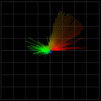
The buttons with green icons offer the simplest figures such as circle, lines and polygons.
 | line mode - a standard graphics mode. |
 | Beam mode - creates the Shape out of dots. |
 | shows static corners - This is option is mainly for beam mode when used with the “beam speed” slider. |
 | show lines - in beam mode it allows the beams to “connect” by means of soft lines. |
 | Works with the Audio tab to display a spectrum analyzer as a polyline. |
 | Works with the Audio tab to display a spectrum analyzer as vertical lines. |
 | Works with the Audio tab to display a spectrum analyzer as horizontal lines. |
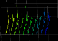
 | Works with the Audio tab to display a spectrum analyzer as vertical lines arranged in a circle. |
 | Works with the Audio tab to display a spectrum analyzer as vertical lines arranges in circle and that moves in both directions. |
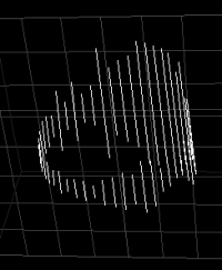
 | Works with the Audio tab to display a spectrum analyzer as grid of vertical lines. |
 | Works with the Audio tab to display a raw audio wave similar to an oscilloscope. |
 | Works with the Audio tab to display an audio wave as a X-Y picture. Note, BEYOND records one channel and this is not a true stereo picture. DANGEROUS MODE! |
 | Works with the Audio tab to display an audio wave as a X-Y picture, but on this vertical lines comes from the center. DANGEROUS MODE! |
 | Opens a Primary Shape from a previously saved file. |
 | Uses the Recorder/FIFO as a Primary Shape. |
| Spectrum analyzer examples | |
|---|---|
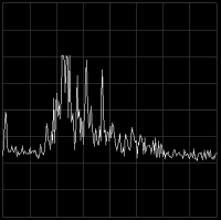 | Polyline |
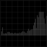 | Vertical lines |
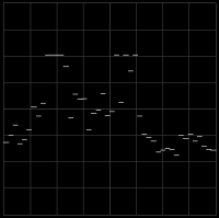 | Horizontal lines |
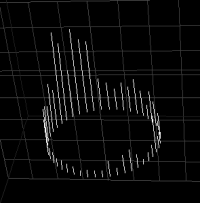 | Vertical lines arranged in a circle |
 | Vertical lines arranges in circle and that moves in both directions |
 | Grid of vertical lines |
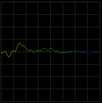 | Wave similar to an oscilloscope |
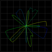 | Wave as a X-Y picture. DANGEROUS MODE! |
 | Wave as a X-Y picture, but on this vertical lines comes from the center. DANGEROUS MODE! |
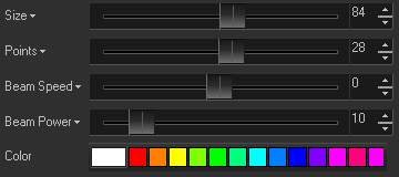
Size - radius of the shape in percent.
Points - number of points in the base shape. Note, the Shape generates vector points; the actual number of points projected can be much higher.
Beam speed - speed of beam scrolling by the shape.
Beam power - number of points in the beam.
Color - an initial color of the primary shape points.
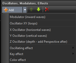
For adding an oscillator or modulator, click on the Add button. In the context menu there are items that specify a Shape object - Modulator, Oscillator, or axis Oscillators.

Amplitude - vertical size of the wave form.
Waves - number of full wave forms applied to the primary shape.
Speed - speed of wave form’s motion.
Time shift - phase of wave form.
The Options menu allows the choice of standard waveforms such as Sinus, Triangle, Square, Sawtooth ,and Blanked Sawtooth. Additional, less traditional waveforms are available such as:
FFT - uses a FFT spectrum array as a waveform.
Audio - uses a raw recorded waveform.
Custom Waveform - opens an editor where you can freeform paint the waveform. See Custom Waveform Editor.
Secondary waveform - allows the modulation of the main waveform.
 | This Button calls a standard Input dialog that allows linking the oscillator/modulator parameters to Channel, MIDI, DMX, and Audio inputs. See Input dialog. |
The Shape has an interesting feature - it can record input to create a waveform from. For recording, the Shape editor uses a circular buffer - FIFO, First In, First Out. There is a high resolution timer that stores the input values into the FIFO stack and the Shape uses the stored information as a primary shape. FIFO stores points - X, Y, Z, and an “Action”. An Action example is brightness.
FIFO is a pure real time tool. It can record FFT Spectrum analyzer bands, MIDI or DMX sliders, Gamepad or Kinect motions, etc. The only limitation is this is only a real time tool. As a solution the Shape offers the use of an Image as a source for FIFO.

Base image section has standard the Open, Paste, Copy, and Delete commands that allow assignment of the base Image.
Motion speed defines the speed of the incoming data of the Base Image to FIFO.
Input for X - defines the source for X axis, see Input dialog for details.
Input for Y - defines the source for Y axis, see Input dialog for details.
Input for Z - defines the source for Z axis, see Input dialog for details.
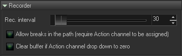
Rec Interval - period of writing data to FIFO in milliseconds. Higher values mean slower recording.
Allow breaks in path and Clear Buffer, an idea came up to try to use a touch screen device to draw on to control a laser. To draw a path on the phone screen (using your finger) that will stop and later disappear (when removing your finger from the touch screen). For making this we need two things. One is the reaction of the touch screen to your finger (down and up), and the ability to clear the touch screen buffer. The Action is really your finger movement (down/up), or mouse down/up flag. Both options make no sense for a FFT recording, but make perfect sense for interactive actions.
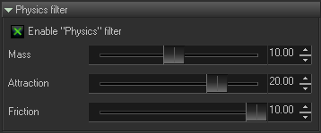
Enable Physics filter - enables the filter; when it is ON, all data will come through the filter. Otherwise FIFO stores raw data, as it is recorded.
Mass, Attraction and Friction are parameters of the mass-spring filter.
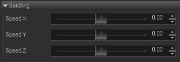
Internal name of this function is Wind. It effects the FIFO points as if they were being blown in some direction. Technically it works fairly simple. Every time a new point is stored in FIFO, BEYOND add an offset to all the currently existing points, defined by Speed X, Speed Y, and Speed Z values. This works great in scenarios like this. X axis is not assigned to Input and has some Speed X value. Y axis is assigned to some Input. As a result, we have sort of a scope, and a diagram of how Input changes the wave form.